How to: Use the SOLIDWORKS Vent Tool
12 September 2025
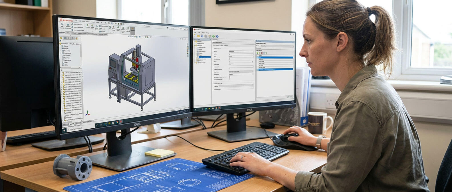
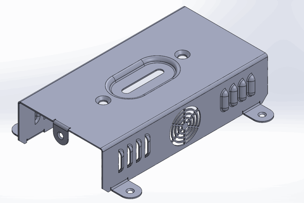
The SOLIDWORKS Vent Tool (also referred to as the Vent feature) is a powerful and versatile function located within the Sheet Metal tab. It enables users to create complex cut-outs quickly, incorporating elements such as ribs, spars and enclosed boundaries, all from a single sketch. Although particularly well-suited to sheet metal, it also works on other parts, creating intricate patterns more efficiently than multiple complex features.
Using the SOLIDWORKS Vent Tool
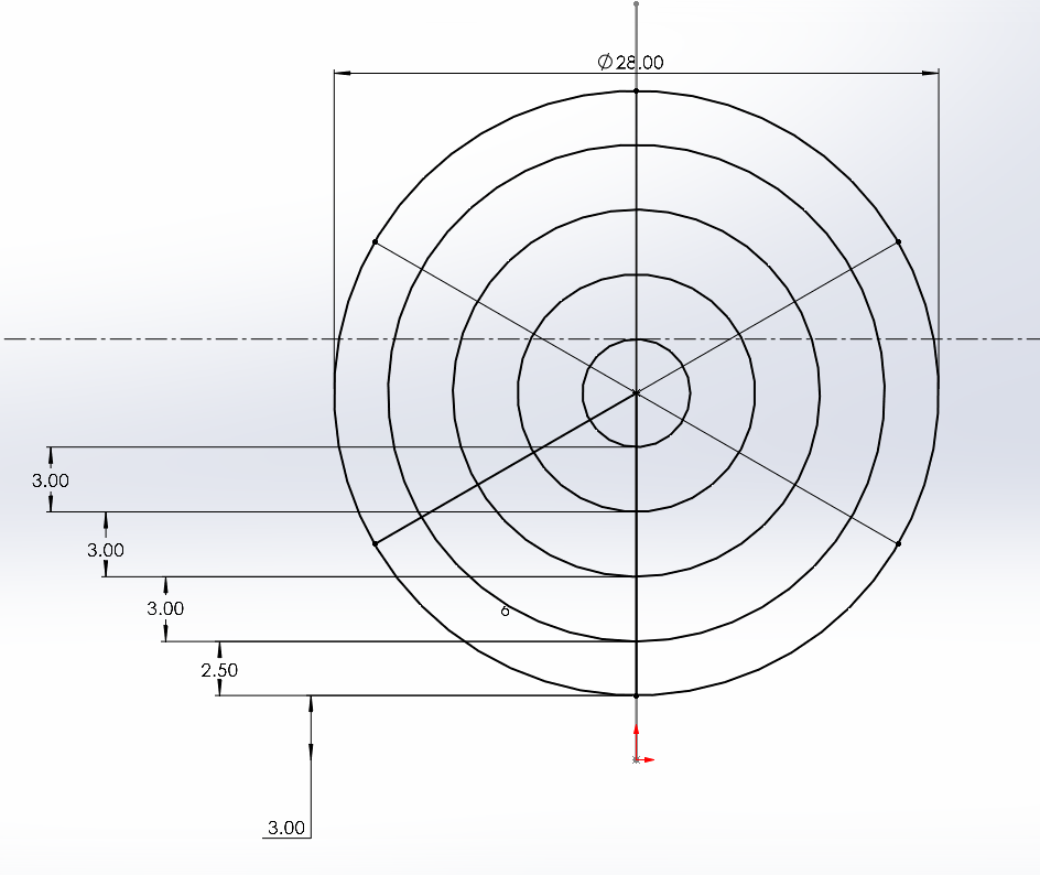
We start by making an appropriate 2D sketch that controls the vent’s shape on one of the faces of the sheet metal component. The sketch should show any ribs and spars.
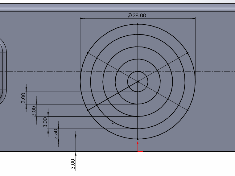
The outer circle in the image above represents our vent’s outer border. Three lines meet the circle at 60-degree intervals and create six spokes. Several offset concentric circles serve as our vent’s spars. The offset values for the first offset circle (2.5 mm) and the others (3 mm) differ. We will examine the significance of this later.
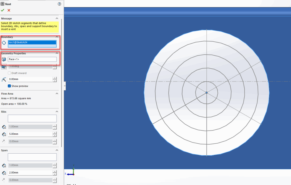
The next step is to launch the vent tool on the sheet metal toolbar. This opens the property manager, where we input the required information.
In the Vent PropertyManager we define the boundary, and face, on the sheet metal part where the vent is placed from within the tool. At this stage, we see a circular hole in our part.
Helpful link: Vent PropertyManager
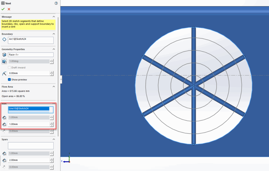
Using the SOLIDWORKS Vent Tool – Ribs
Next, we define the ribs. We select the straight lines in the sketch and set the rib width in the property manager.
Using the SOLIDWORKS Vent Tool – Spars
It’s possible to select the concentric circles as well, but we want them to have different widths, so we apply them as spars.
We then select all the remaining concentric circles as spars, except for the innermost one.
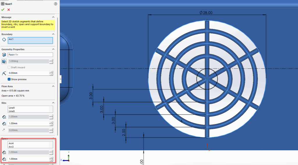
We don’t select the inner circle because we want to fill that region with material. To do this, we go to the ‘fill in boundary’ section in the property manager and select the inner circle. We can also add fillets to all sharp edges by returning to the ‘geometry properties’ area and setting a fillet value.

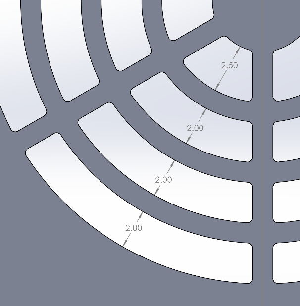
From the images below, the apertures at the outer boundary have the same width as all the others except the innermost. This happens because we set a different offset value on the outside to allow for the width of material applied to the spars along the middle of the sketch line. To achieve the same aperture on the inner boundary, we change the offset dimension from 3 mm to 2.5 mm.
In the previous images, some commands in the Vent tool property manager are greyed out. This happens because of the sheet metal component we’re working with. For non-sheet metal parts, you can add draft angles, adjust rib thickness, and set vent or spar height offsets.
That’s how to use the SOLIDWORKS Vent Tool!
I hope you found this Sheet Metal tutorial useful. If you’d like to see more, head on over to our tutorials and resources archive here!

|
About the Author: This tutorial was written by SOLIDWORKS Applications Engineer, Cameron Piper. Cameron has been with the Visiativ Technical Support Team since 2021. |
|||
|
|
View Cameron Piper’s LinkedIn Profile here.
|
|||