

How to: Create Custom Sheet Metal Forming Tools in SOLIDWORKS
11 July 2025
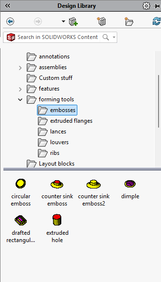
The SOLIDWORKS Design Library includes a predefined set of forming tools specifically designed for punching sheet metal models. Using these is straightforward – simply drag a tool from the Design Library onto the face of a sheet metal part, then position and orient it as needed.
To access them, navigate to the ‘Forming Tools’ folder within the Design Library. You’ll find a variety of useful features here, including ribs, lances, louvers and extruded flanges.
 |
While you can modify the size of standard forming tools by opening their models and adjusting the dimensions, creating a custom-shaped forming tool requires a specific procedure to ensure the desired outcome.
Here’s how to do it:
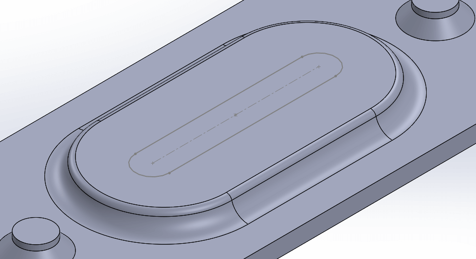
The first step is to create the desired geometry that you’d like to punch into your model. Initially this can just be a very basic sketch and extrude drawn out on a flat plate. You can add fillets to the inside corner to create a radius in the sheet metal model.
In the example below, the middle of the top face removes a slot from the sheet metal model. To make this work, you need to draw a sketch that defines the area to be removed. Then, project this sketch onto the model and use the ‘Split Line’ command to divide the top face into two separate ones (since there’s only one face initially). You can find the ‘Split Line’ command under Insert > Curves > Split Line.
Always remember that when you create the geometry for a forming tool, the internal radius at the inside corner limits the sheet thickness you can use. For example, a 3 mm radius only works with sheet metal up to 3 mm thick. Any thicker and the sheet metal model will intersect.
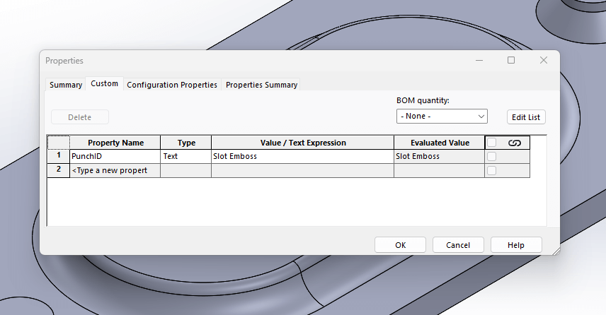
Once the forming tool shape is complete, add a ‘Punch ID’ to the custom properties menu (File>Properties). By including this information, any ‘Punch’ tables generated from the resulting sheet metal models will read the relevant data from the custom forming tool.
The Forming Tool Command
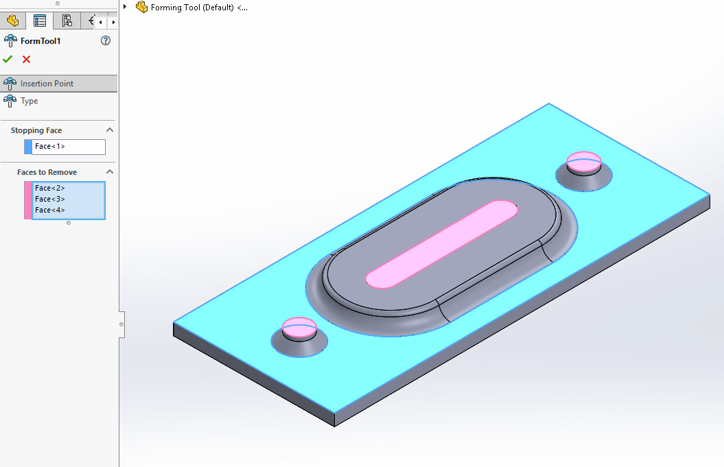
You can now set up the model using the ‘Forming Tool’ command on the Sheet Metal toolbar or by going to Insert > Sheet Metal > Forming Tool.
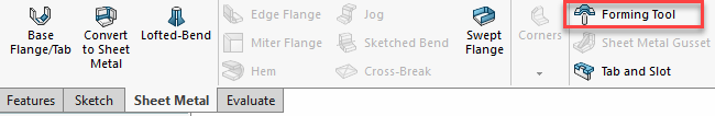
This command includes two property boxes: a blue one for the stopping face and a pink one for the faces you want to remove.
Saving the Forming Tool
Now that you’ve finished the file, you have two choices for saving it:
- Saving the files in the Design Library\Forming Tools\ as any SOLIDWORKS part (.sldprt/.sldlfp/.sldftp)
- Saving the files in any folder on your machine, but saving it as a SOLIDWORKS forming tool part (.sldftp)
You can find all the necessary file types under File > Save As. Drop down the ‘save as type’ to find the various options.
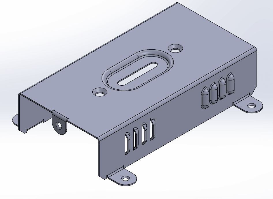
Creating custom forming tools in SOLIDWORKS might seem complex at first, but with a bit of practice it becomes second nature. By mastering this process, you’ll unlock greater flexibility in your sheet metal designs and save valuable time on future projects.

|
About the Author: This tutorial was written by SOLIDWORKS Applications Engineer, Cameron Piper. Cameron has been with the Visiativ Technical Support Team since 2021. |
|||
|
|
View Cameron Piper’s LinkedIn Profile here.
|
|||