
How to Use Manufacturers Parts to Create Cpoints in SOLIDWORKS Electrical 3D
19 May 2026
Looking to create CPoints in SOLIDWORKS Electrical 3D? This guide explains the steps you need to prepare a SOLIDWORKS part for routing wire and cable, using the manufacturer’s part details from SOLIDWORKS Electrical Schematic. For this to work, you’ll need access to the SOLIDWORKS Electrical 3D add-in. We must insert “C Points” so that SOLIDWORKS can determine where to connect the wires to your part.
Step 1: Acquire or make the part.
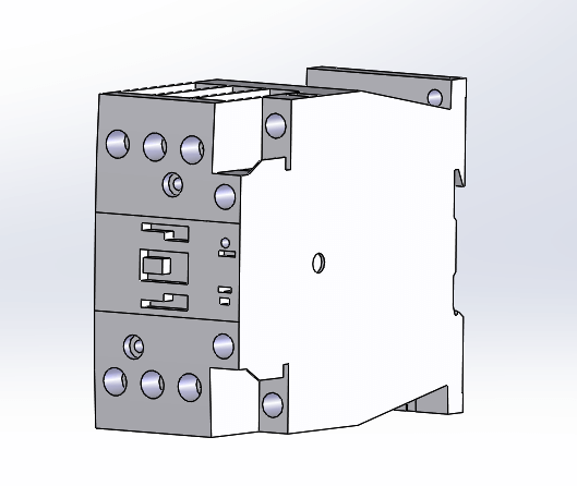
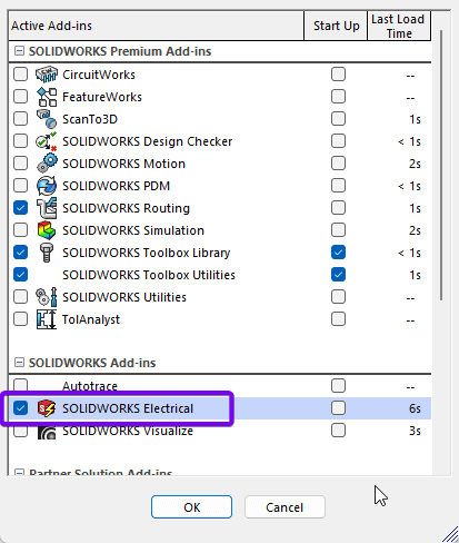
It doesn’t matter if you’ve made the part or downloaded a CAD file from a manufacturer’s website. The model should be saved in an appropriate location for later use in your assembly. I’ve chosen a contactor to demonstrate this process. I’ve also made sure I have the SOLIDWORKS Electrical add-in turned on.
Step 2: Manufacturer part data
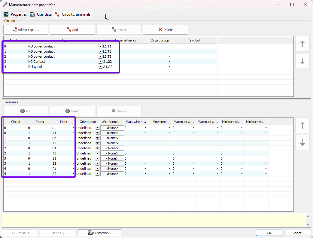
The second step in creating CPoints in SOLIDWORKS Electrical requires manufacturer part data. The manufacturer part data should be added to the SOLIDWORKS Electrical Manufacturing part library. I’ve covered these steps in a previous post, “How to create a Custom Symbol in SOLIDWORKS Electrical”. Here are the circuits from the manufacturer’s parts data I will be using.
Step 3: Open the Electrical Component Wizard
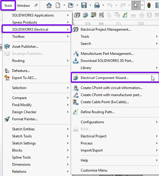
You can find the Electrical Component Wizard in the SOLIDWORKS Electrical 3D toolbar or in the Tools > SOLIDWORKS Electrical menu.
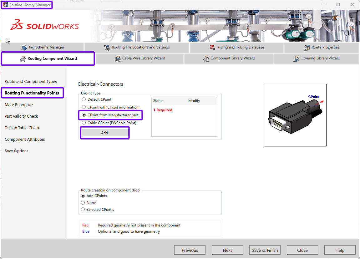
The Routing Component Wizard tab appears in the Routing Library Manager. You’ll already be fast-forwarded to the routing functionality points section. We shall select “CPoint from Manufacturer part” and click “Add”.
Step 4: Adding the connection points (CPoints)
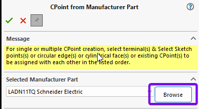
In SOLIDWORKS, click on the “Browse” button to search for a manufacturer’s part if it isn’t already in the drop-down.
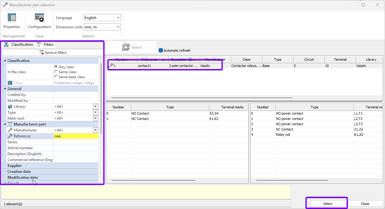
Search for the manufacturer’s part. Highlight the part and press “Select”.
a) Rotate the model to view the area where you’ll connect the wire.
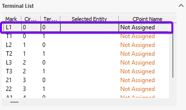
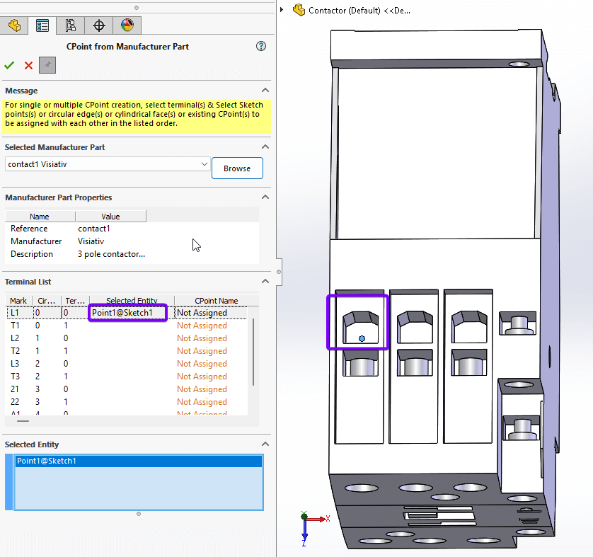
b) Select the first terminal that you wish to insert from the Terminal list in the “CPoint from Manufacturer part” property manager.
.
c) Click a point on the model where the wire will be terminated. SOLIDWORKS will ask you a “Do you want to create a new sketch point?” Select “Yes”. SOLIDWORKS adds a sketch point to the selected face at the spot you clicked – this marks the start of the Cpoint. The “Selected Entity” column then updates with this information.
Inserting more CPoints
If you wish to insert more CPoints in the same operation, hold the “Ctrl” Key and select another terminal from the list. Then select an appropriate location to place the terminal as above, using the left click. (Note: don’t click on another terminal in the list without holding “Ctrl”, or it will switch which terminal is related to which sketch point.) Sometimes it’s best to do a few on one side of the model. Click the green tick to confirm the creation of these CPoints, then continue. (Before you click OK, make sure you’ve toggled on the pin icon so the property manager stays open).
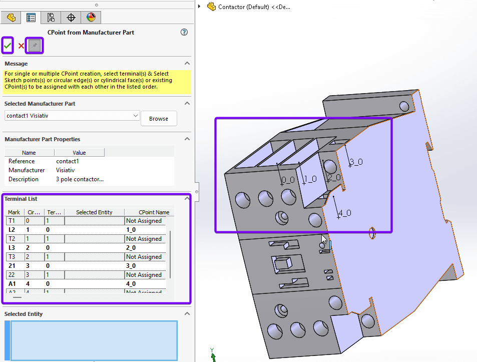
Insert any remaining CPoints in the same manner. Click “OK” to confirm creation. If you accidentally close the manager, you can always reopen it from the Routing Library wizard, by clicking on the “Add” button again. Place the remaining terminals on the other side of the model. Any terminals not placed will have “Not Assigned” written in the “CPoint Name” column.
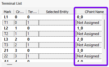
The terminals I placed are numbered according to the circuits and terminals in the manufacturer’s part. (Note numbering starts at zero for 2_0 is circuit 3, terminal 1)
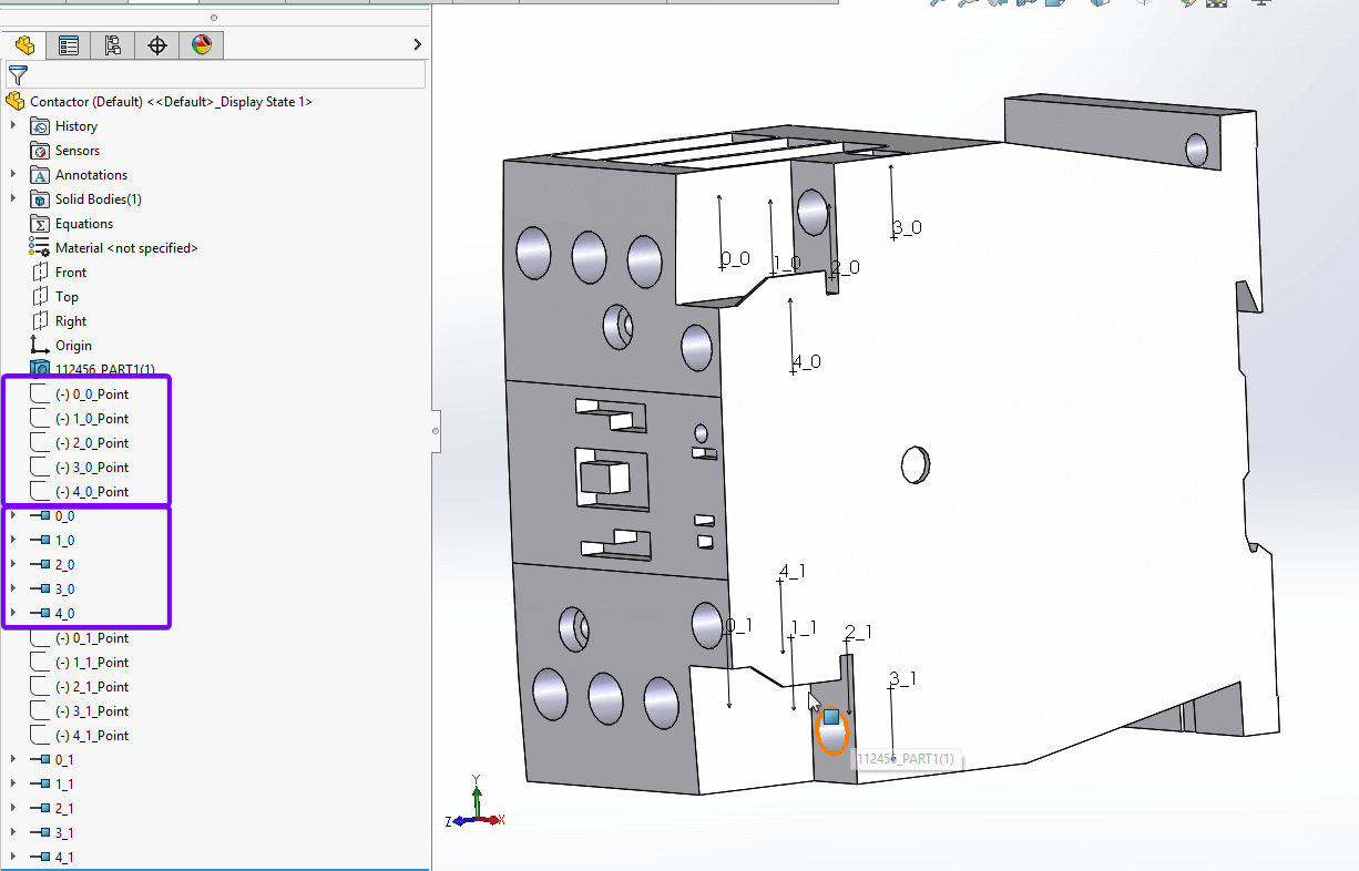
The image above shows that I added the terminal in two batches. Each CPoint has a corresponding sketch, matched by the naming convention of circuit and terminals. You can move the sketch point by simply editing the relevant sketch to place the CPoint more accurately.
Close the property manager and return to the Routing Library Manager. Click on the “Next” button to proceed.
Step 5: Mate references
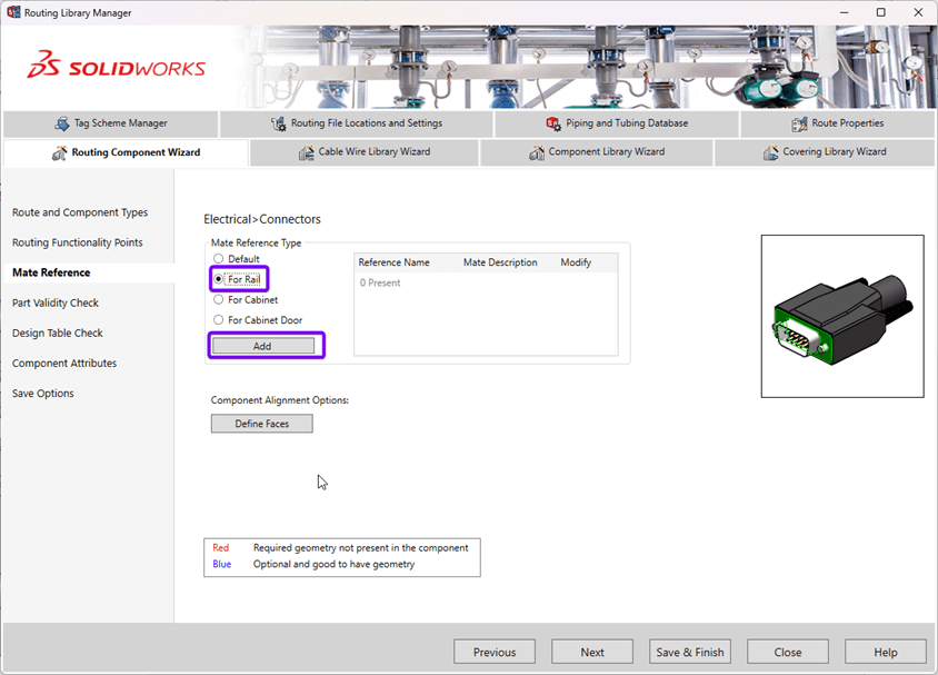
Mate references help you quickly place components. It’s predefining the assembly mate you wish to add when placing a component. When the component and the part it’s put onto have matching mate references, they snap together. In our case, we’ll add a special type, as this will be a rail-mounted component in a cabinet.
Select “For Rail” and click the “Add” button.
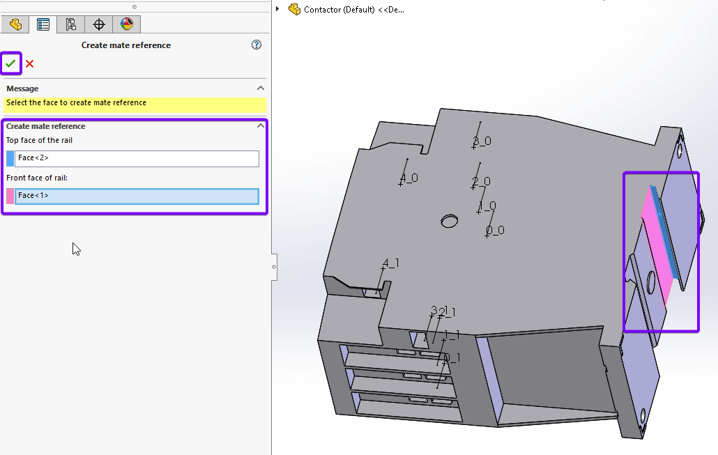
Select the appropriate faces for the top of the mounting rail (highlighted blue) and the front of the rails (highlighted pink) so SOLIDWORKS knows which mates to add to mount the component correctly on the rails. (Note: your rails components need the corresponding rail mates applied using the component wizard) Click “OK” to confirm your choices. Now return to the Routing Library Manager.
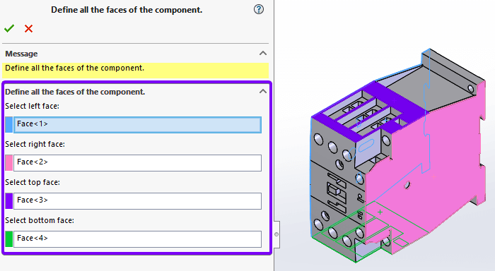
Step 6: Defining Faces
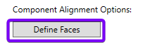
We need to define the faces of a component so SOLIDWORKS can identify which face to use when spacing components. Click on “Define Faces”.
 |
Now select the faces on the model as if you’re looking at it from the front. Once happy with the selection, click “OK”. Now save the part and close the Routing Library Manager.
And there we have it, we’ve created a Cpoint in SOLIDWORKS Electrical. We’ve prepared our part so we can place it in our electrical assembly and route wiring to and from the part. If you need any help with this, and are covered by our support service, please contact our support team and we’ll be happy to help. Happy routing!
 |
About the author: This guide was written by SOLIDWORKS Applications Engineer, James Kingman. James has been with the Visiativ Technical Support Team since 2024. |
|||
|
|
||||