

SOLIDWORKS Simulation VS Hand Calculations
20 April 2026
SOLIDWORKS Simulation is an exceptionally robust tool designed to handle a wide variety of studies. A common question we encounter when discussing simulations is about the accuracy of the results. To ensure reliability, SOLIDWORKS collaborates with NAFEMS (National Agency for Finite Element Methods and Standards), which validates the software against real-world industry challenges. This can be reviewed by going to Help > SOLIDWORKS Simulation > Validation. This blog examines one of these examples, specifically a Cantilever beam problem. Below is a comparison of SOLIDWORKS Simulation vs hand calculations
The Problem
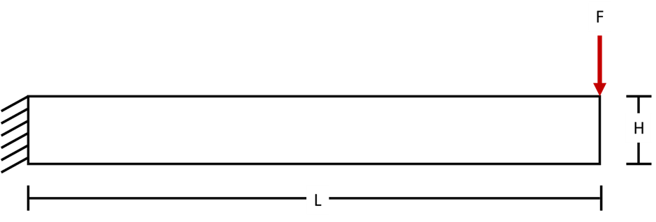
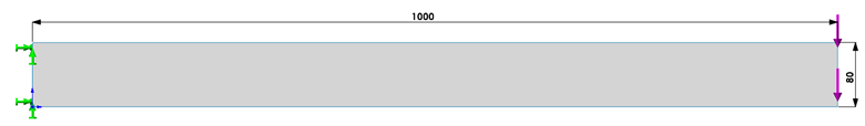
The beam below is designed to be supported at one end while the other end remains free. A downward load is applied at the free end of the beam. Our objective is to determine two key factors: the deflection at the free end of the beam and the stress at the supported end.
The given values:
Force (F): 4500N
Length (L): 1m
Elastic Modulus (E): 2.1×10¹¹ N/m2
Thickness (T): 10mm
Height (H): 80mm
Poisson ratio :0
Hand Calculations
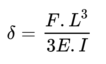
To calculate the deflection at the free end of the beam, we use the formula:
 |
|---|
where:
(F) is the load applied at the free end (in Newtons)
(L) is the length of the beam (in meters)
(E) is the Young’s modulus of the material (in Pascals)
(I) is the moment of inertia of the beam’s cross-section (in meters4)
Second moment of inertia (I)
 |
|
|---|
Deflection:
 |
|
|---|
To calculate the stress at the fixed end of the beam we use the formula:
 |
|---|
And:
 |
|---|
( c ) is the distance from the neutral axis to the outer fibre (in meters
 |
|---|
Stress at support:
 |
|---|
SOLIDWORKS
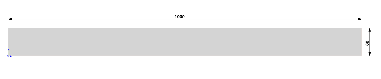
We can model the beam as a 3D shape or represent it as a surface, using SOLIDWORKS Shell meshing. Shell meshing greatly reduces calculation time for suitable studies. We model the beam below using the following dimensions (mm).
We have created a study in the Simulation module.
The material properties specified in the problem include the elastic modulus and Poisson’s ratio. We created a custom material incorporating these properties and applied it to the surface of the model.
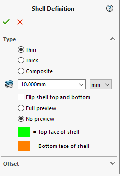
When working with shell elements, unlike 3D meshes, it is essential to define the thickness of the model within the shell definition. In this example, the cantilever beam has a thickness of 10 mm. To include this in the simulation, right-click on the part in the simulation window and add the thickness to the shell definition.
 |
|---|
Now that our model accurately represents the beam described in the problem, we can therefore proceed with applying the fixture and load. We will constrain the leftmost edge of the beam, where it connects to the wall. This means it will have no translation or rotation, allowing us to use a standard fixed geometry constraint here.
Next, we need to apply the force to the right edge of the beam. We use a reference plane to ensure the force is applied in the correct direction. In this case, we will use the front plane and align the force along this plane.
We then run the study.
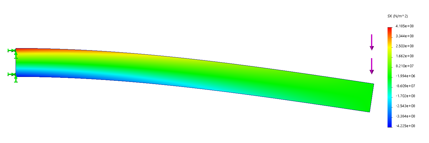
Below is the Normal stress plot for X axis with a max stress of 4.22×10⁸ N/m2. Showing the max stress located at the supported end of the beam.
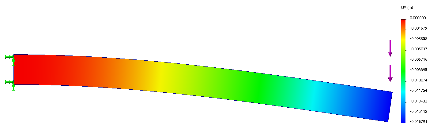
Plot showing the displacement in the Y direction, with a max displacement of 0.0168m at the unsupported end of the beam.
Evaluation
|
|
Hand Calcs |
Simulation |
Percentage difference |
|
Stress |
4.218×10⁸( N/m2) |
4.224×10⁸ (N/m2) |
0.17 |
|
Displacement |
0.016741(m) |
0.016791(m) |
0.29 |
This simple exercise serves to validate the accuracy of SOLIDWORKS simulation software by comparing its results with theoretical hand calculations. Such exercises are invaluable for gaining a deeper understanding of the software’s capabilities and demonstrating how it can streamline the design process through easy and efficient virtual testing.
I hope you found that useful! Make sure to check out our other SOLIDWORKS guides and tutorials here.
 |
About the Author: This tutorial was written by Elite SOLIDWORKS Applications Engineer, Cameron Piper. Cameron Has been with the Visiativ Technical Support Team since 2021 |
|---|