How PLM can help Mechanical Designers
02 May 2025
I’m Simon Dass, Visiativ Products Manager here at Visiativ UK and Ireland. In a previous previous article I gave a broad overview of the Product Lifecycle Management (PLM) process. Specifically, how PLM affects R&D activities in the early part of the product lifecycle. A major activity in R&D is product design, from early concepts to detailed design – that’s what we’re going to be looking at today.
Multiple design disciplines are required to develop a physical product. Some of these design disciplines are:
- Mechanical design
- Electrical design
- Software design
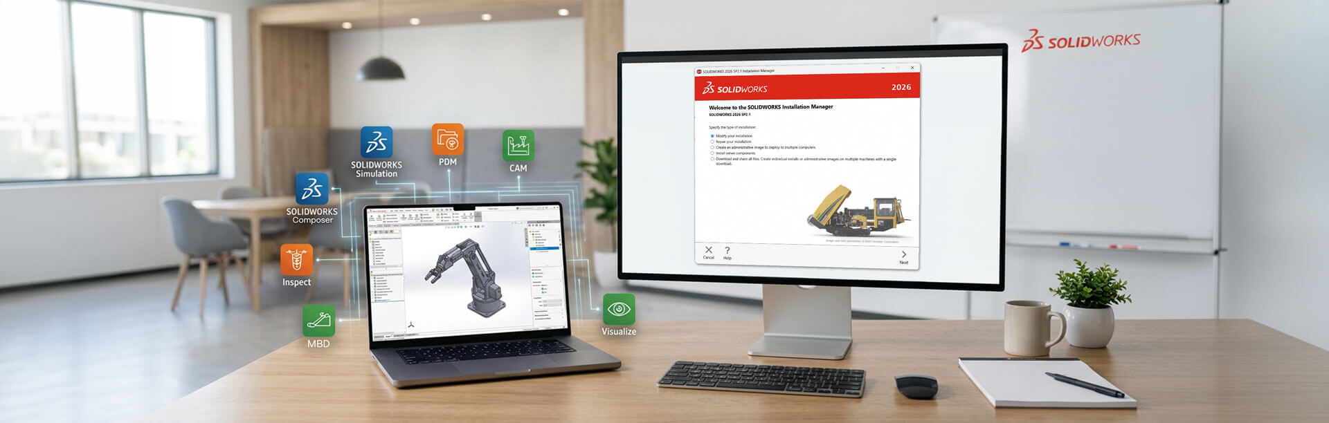
The end user of the product will most likely interact with the product’s mechanical form. Most, if not all, mechanical design is done using Computer Aided Design (CAD) tools. CAD is used from concept through to detailed design. CAD is critical to the design process, and 3D CAD tools like SOLIDWORKS (for mechanical design) are the norm.
Mechanical Design with CAD
If a product is developed in 3D CAD, every component will need its own 3D model. The product’s form and function will be designed and assessed in the CAD tool. And by bringing together individual 3D models into 3D assemblies, the fit (clearances and interferences) and motion can be analysed. 3D models prove very useful for virtual testing with simulation tools. Early physical testing can be achieved by 3D printing the CAD files. And the eventual manufacturing can use the CAD data with Computer Aid Manufacturing (CAM) systems.
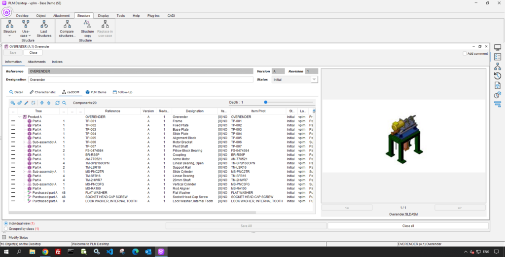
Visiativ PLM CAD BOM
You need 2D CAD drawings for manufacturing, alongside the 3D models. During the design process, you generate various documents. Expanding the use of 3D CAD to Production Engineering (e.g., tooling design) inevitably creates a vast amount of CAD data, file references, and documents. Managing multiple concepts and iterations for each product component (or its tooling) becomes essential. Without proper control, costly mistakes occur—such as using incorrect information to manufacture parts, leading to expensive rework or complete scrapping.
Even today, all types and sizes of product design and manufacturing businesses will not have control of their CAD data.
How a PLM system help manage Mechanical CAD
There are several challenges specifically around controlling CAD data. Let’s see what the challenges are and how a PLM system can help address them.
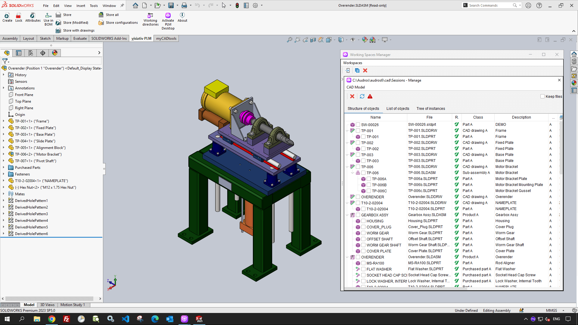
Finding and Storing CAD data
Unmanaged CAD data is often scattered across multiple locations (server drives, local drives), making it difficult to locate. Designers struggle to determine the version or revision of the CAD file once they find it. For 3D CAD assemblies, identifying component revisions becomes even more challenging. When creating new CAD data, you manually assign part numbers by copying and pasting information from other registers or systems. You may also need to generate additional ‘neutral’ formats like STEP or PDF from the CAD files manually. And as you’re saving the CAD data, you’ll have to manually browse a folder structure on a server or local drive and chose an appropriate file name.
Finding and storing CAD data manually raises questions like:
- How do I quickly find CAD data using search keywords?
- How do I know what version of the CAD data will be loaded?
- How can part numbering be made quicker?
- How can neutral files be automatically created?
PLM can help by:
- Speeding up finding CAD data based on criteria (rather than memory or manual searching) as all the data is in one centralised and indexed system.
- Improving decision-making when retrieving and opening CAD data by seeing the version of the components to be opened.
- Increasing the efficiency of part number generation by automating the process.
- Reducing the manual effort of generating neutral files by automating the process during storage into the PLM system.
Controlled Collaboration
Design requires collaboration. In a team developing a product, you must know who is working on each part of the design. This becomes crucial when editing CAD files, as accidental file overwrites often occur. The risk of overwrites increases when the design team stores CAD files in server locations with full write access.
Designing in a team, with CAD data on a shared server location, raises questions like:
- How can I stop anyone editing the CAD file that I’m working on?
- How do I know if anyone is working on a CAD file?
- How do I know who has made edits to a CAD file?
PLM can help by:
- Reducing accidental overwrites by allowing CAD files to be ‘locked’.
- Improving collaboration by seeing who has locked what files for editing.
- Increasing visibility of who edited data and when through version history.
Linking Data / Design Reuse
The links between CAD data is well known. Links such as CAD-to-CAD links for 3D assemblies and their 3D components but also links between 2D drawings and their source 3D models. These links are handled by the CAD system itself. But what if you needed to relate Documents to the CAD data? For example, documents for specifications or test results could be both classed as design data, but the CAD system is not the ideal place to link these documents to the CAD files.
As a manager without access to a 3D CAD tool, you might need to add components to the CAD assembly structure during development. You might also create a new design from an existing one and replace certain parts, all without using the 3D CAD tool.
Manually working with Documents and CAD structures raises the following questions:
- How can I link documents to CAD files to show they are related?
- How do I add components to a CAD assembly structure without the CAD tool?
- How can I duplicate an existing design and replace some parts?
PLM can help by:
- Improving visibility of how design data is related by providing simple drag & drop linking between files.
- Improving collaboration in design by allowing additions to the CAD assembly from the PLM environment.
- Increasing efficiency in design reuse by using PLM tools to copy CAD structures and also swap out components.
Revisions & Approvals
As the product’s design evolves, you update CAD models to reflect changes. You eventually issue these updates as new revisions or versions. Using file servers, you manually create new iterations of the CAD data, which becomes a time-consuming file management task. You archive or move old versions and manually update file properties or title blocks.
Along with creating the new version, you obtain sign-off or approval for the design update. This process changes the design’s maturity from its Initial state to its final Released or Valid state. In a manual approval process, participants typically exchange emails with attachments. After final approval, you manually document the maturity state, the approver’s name, and the approval dates, often in the 2D CAD drawing title block.
Manual revision control and approvals raises the following questions:
- How can I improve the creation of both minor and major revisions?
- What lifecycle stages are the CAD files currently in for a product?
- How can participants in the approval process be selected and notified?
- Can the revision and approval information be automatically populated in the drawing?
PLM can help by:
- Increasing the efficiency of creating new revisions by automating the CAD file management required.
- Improving the understanding of the maturity of CAD data by highlighting the maturity status.
- Improving collaboration in the approval process by simplifying approver selection and notifying participants.
- Improving data accuracy due the removal of manual data inputs for the revision and approver names/dates in CAD files.
How can Visiativ help Mechanical Designers with PLM?
You may have recognised some of what was described above. Your current practices for Mechanical CAD data during the Product Lifecycle Management process may be manual and time-consuming. Visiativ PLM’s integration with multiple Mechanical CAD systems means you can focus more time on designing in CAD and less time with CAD data and file management.
Visiativ have decades of industry knowledge around Product Lifecycle Management and its various sub-processes like Mechanical Design. We can help businesses improve R&D efficiency, compliance, and productivity, whether they focus on Product Data Management or broader PLM. With our PLM expertise, we’ll work with you to enhance your Product Lifecycle Management for Mechanical Design.
If you need help with your PLM process, get in touch with our experts today.
|
|
About the author: This guide was written by Visiativ Products Manager, Simon Dass. Simon has been implementing PDM and PLM systems since 2006. |
|||
|
|
View Simon Dass’ LinkedIn Profile here.
|
|||