


How To: Use the Measure Tool in SOLIDWORKS
19 August 2024
The SOLIDWORKS Measure tool can be used to measure the distance, angle, and radius in sketches, 3D models, assemblies, or drawings. This makes it a very potent tool in the SOLIDWORKS user’s arsenal – read on below for an easy guide on how best to use it!
SOLIDWORKS Measure Tool
The SOLIDWORKS Measure Tool is a quick way to verify the dimensions of a part, assembly, or drawing. This tool is preferred over other methods when the purpose is for inspection only. Other methods such as creating reference geometry with Smart Dimension or entering a sketch can be more tedious and time-consuming.
The Measure Tool can be accessed from the Evaluate tab within SOLIDWORKS.
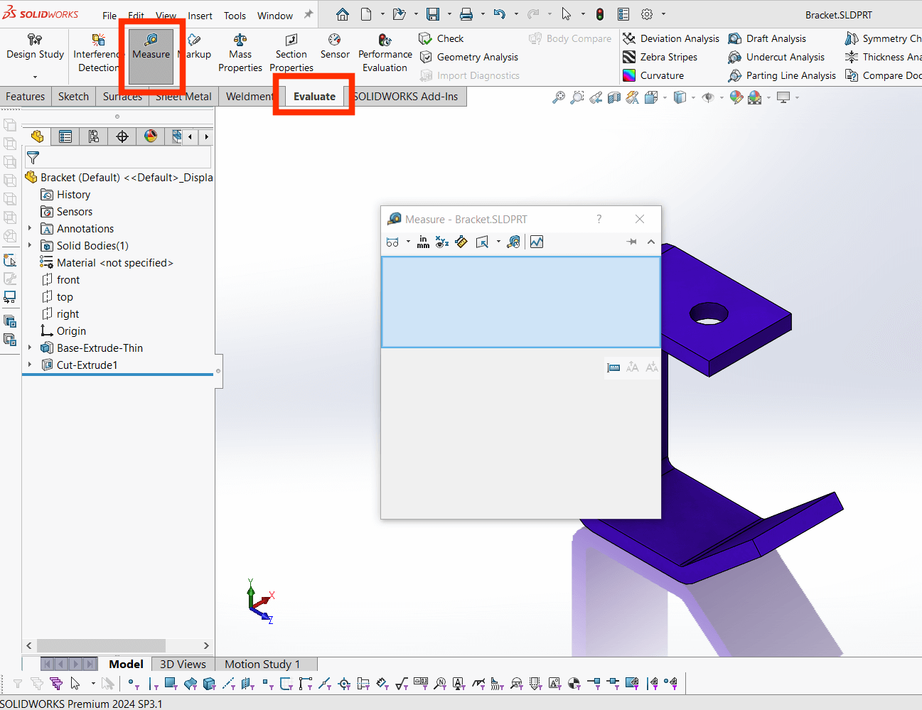
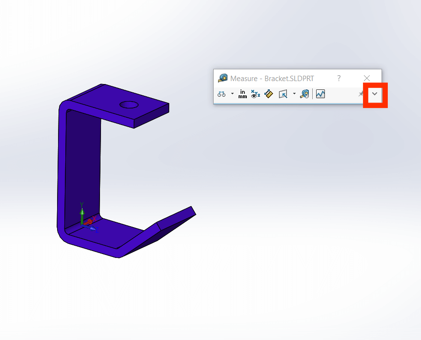
When you first activate the measure tool your cursor be replaced with a measuring tape icon. Note that if the measure property manager window is collapsed, it can be expanded using the grey dropdown arrow.
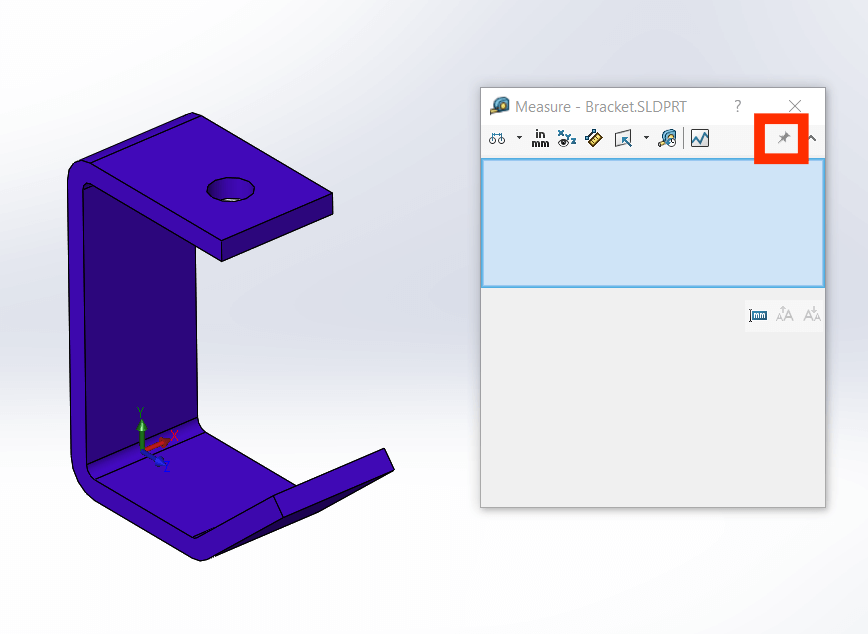
Close the measure dialog box by simply pressing the Esc button. If you want to keep it open, select the pin icon to pin it to the graphics area.
Tip
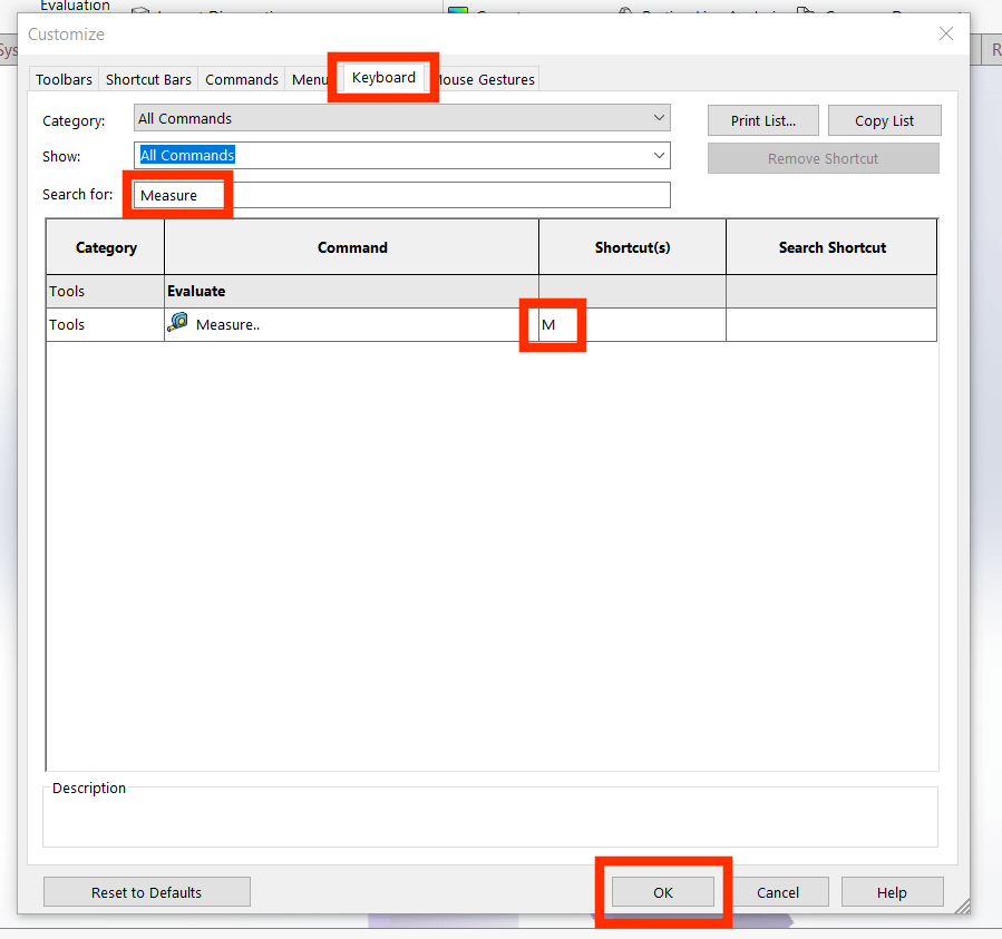
If you use the measure tool often, a tip would be to add a keyboard shortcut key using the customize options. For example, I have set the ‘M’ key as my shortcut for accessing it. Access the customize menu by selecting Tools > Customize.
Covering the Basics
The measure tool allows you to measure distance, angle, and radius. It is also possible to measure the size of and between, lines, points, surfaces and planes.
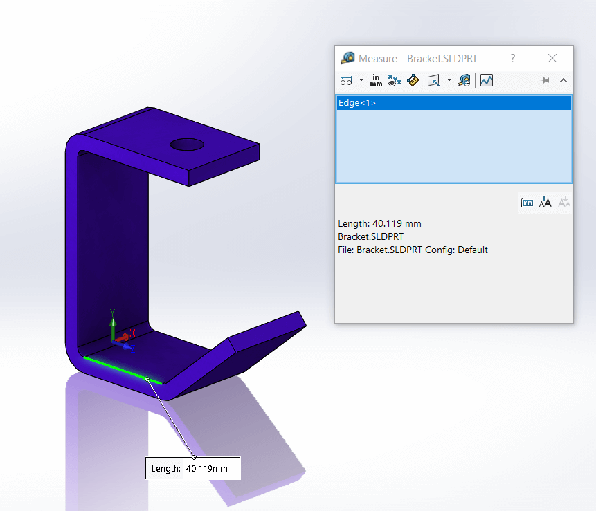
- Simply select an edge of a model to obtain the length.
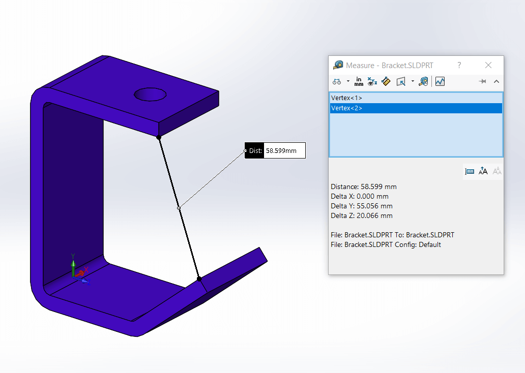
- Select between two points.
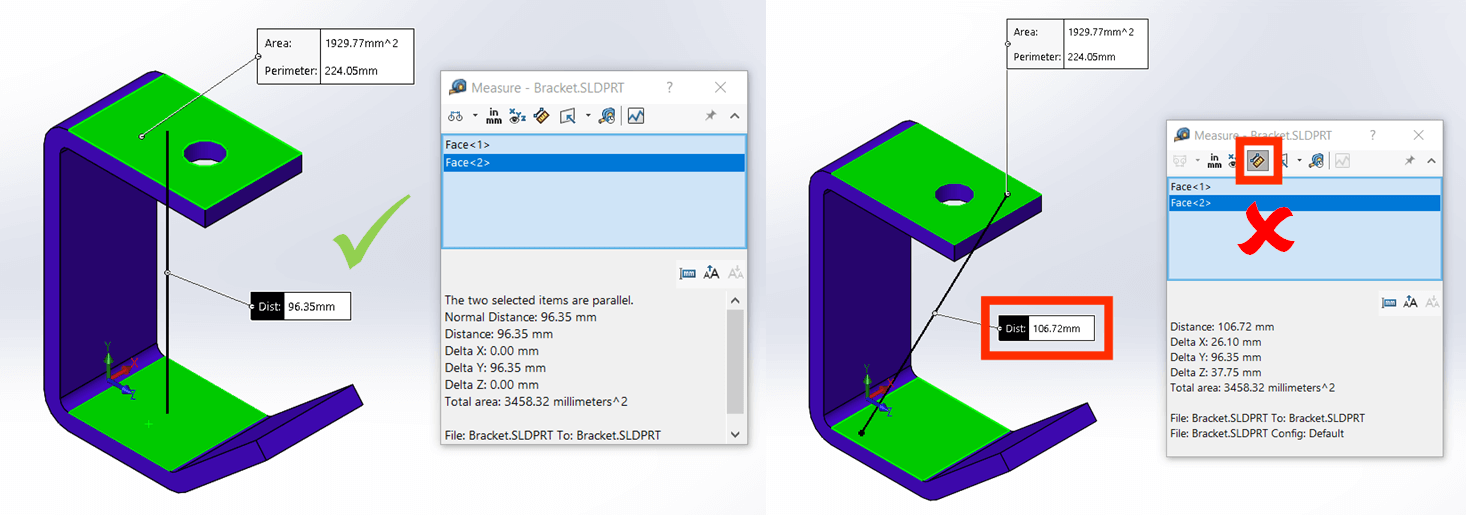
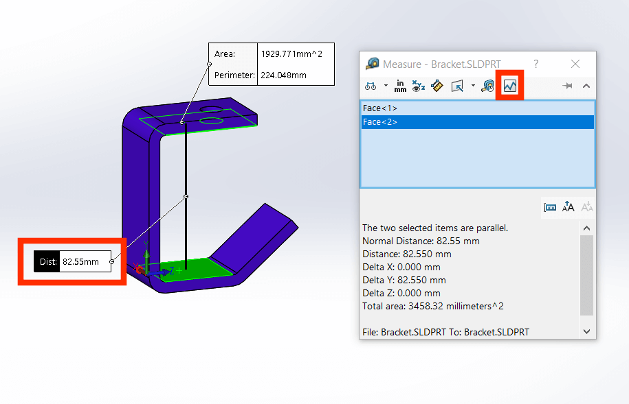
- Select two parallel faces to obtain a distance between them. Ensure that the point-to-point option is not checked on.
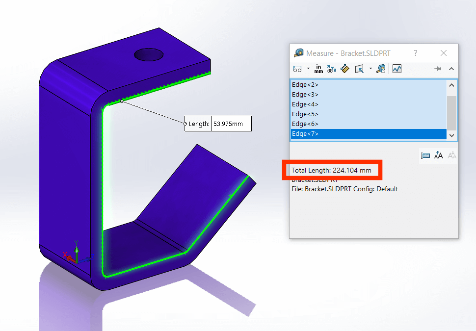
- Selecting multiple edges will produce a combined length. Be careful not to confuse the total length highlighted below, with the length of the last edge selected.
- To obtain an angle, select two edges or faces. The edges or faces cannot be collinear or parallel to one another.
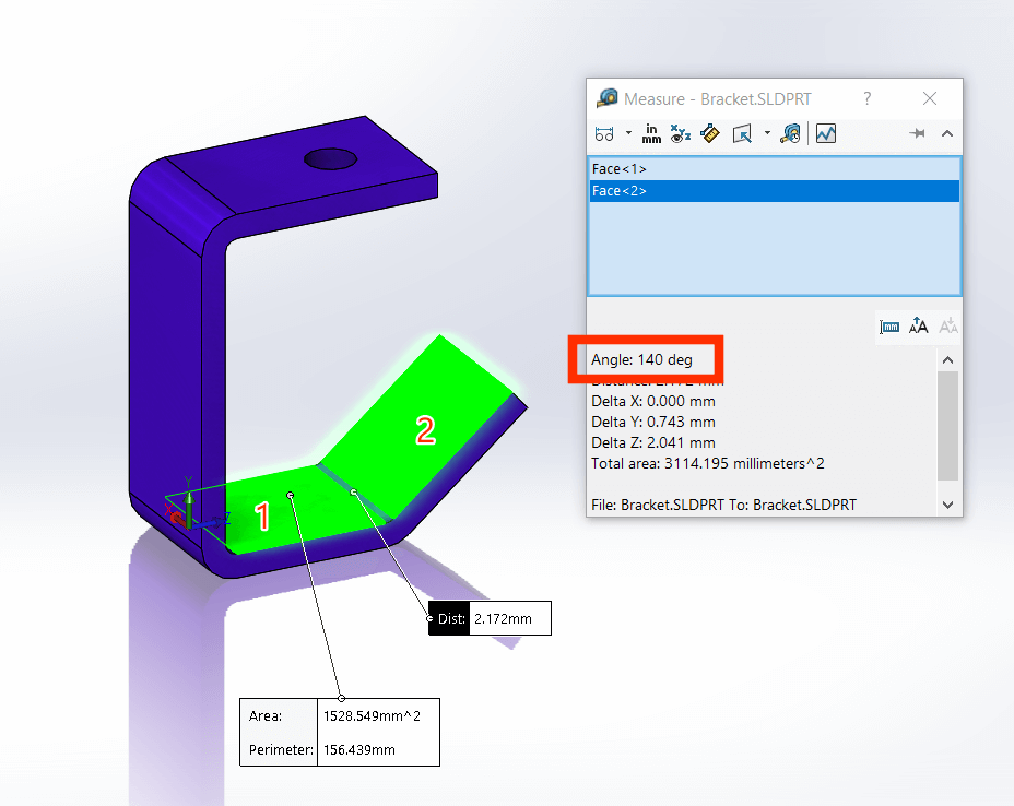
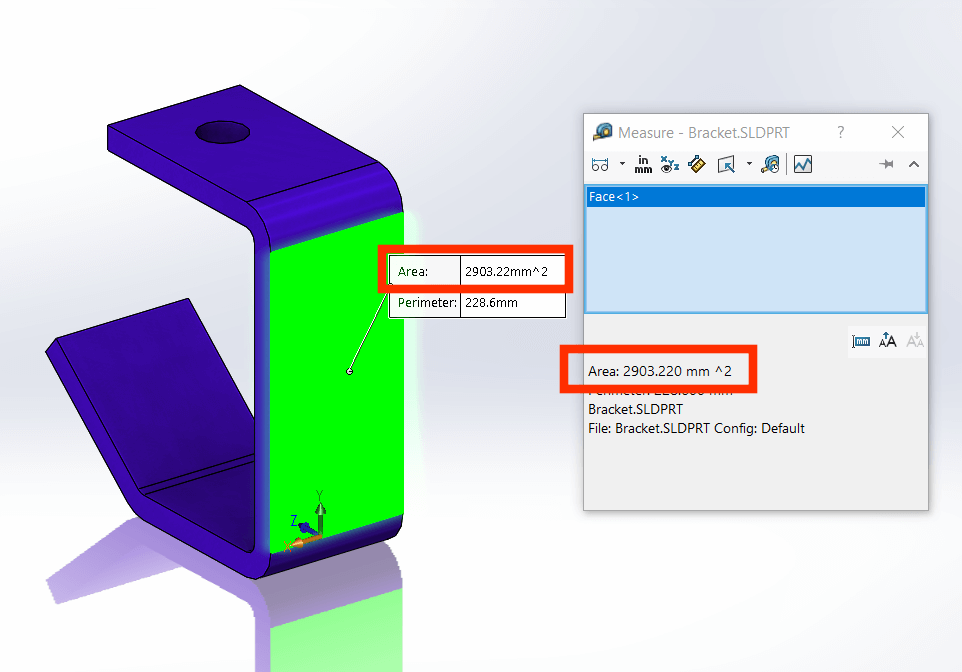
- Select a face or series of faces to obtain the area/total surface area. You do not need to hold ctrl when making multiple selections.
`
Arc and Circle Measurements
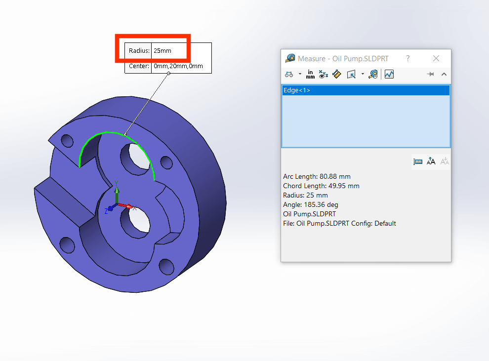
Select a circle to obtain a diameter dimension and an arc to obtain a radius.
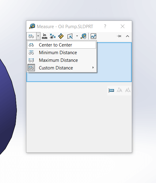
The default measurement when selecting two arcs/circles is center to center, however, expanding the Arc/Circle Measurements list will give you some additional options. These include the maximum and minimum distance between selections and a custom option.
Additional Measure Tool Options
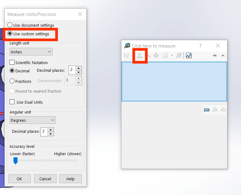
Units/Precision
Specify a custom measurement and unit precisions. Note that if custom settings are applied, they will be applied each time you use the measure tool unless it is switched back to ‘Use Document Settings’. Dual dimension settings can also be applied here.
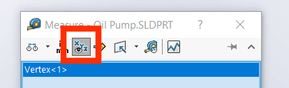
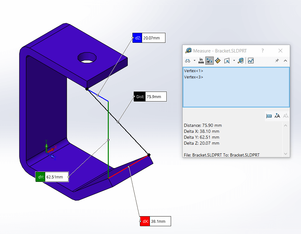
XYZ Measurement
This displays the dX, dY and dZ dimensions between selected entities.
Measurement History
List all previous measurements taken in the current session
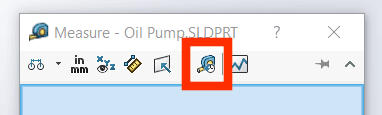
Create Sensor
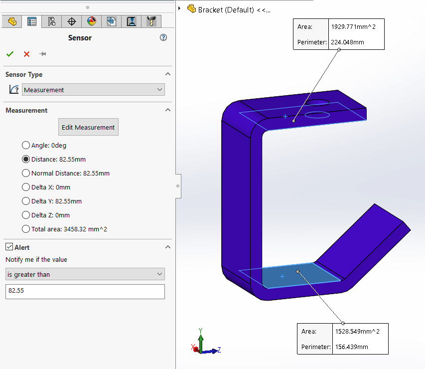
Use this option to set SOLIDWORKS to warn you when a measurement changes. In the example below, we will set a sensor to alert us when the dimension exceeds its current value.
Set the desired sensor parameters in the Sensor property manager.
When the dimension exceeds the set value, a warning can be seen in the feature manager design tree.
Measure the Projected Surface Area of a Body
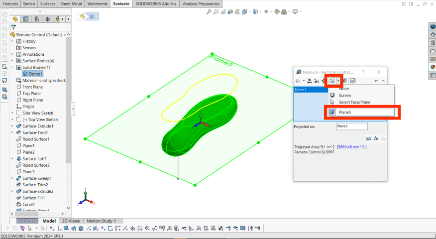
This option allows you to measure the projected surface area of selected faces or bodies. The ‘Projected On’ plane can be a default or reference plane.
Thank you for reading our latest SOLIDWORKS ‘How To’ guide! If you require further assistance on using this tool, or have any further enquiries, you can check out our Support page for Visiativ customers here!