

How to: Use a DXF Mapping File With SOLIDWORKS Sheet Metal
30 June 2025
Did you know that you can export a sheet metal flat pattern directly as a DXF file from SOLIDWORKS? Not only this, you can control how different elements – such as model edges, bend lines and form tools – are assigned to specific layers using a DXF mapping file.
To get started, simply follow the steps in this guide from SOLIDWORKS Applications Engineer, Sam Barlow.
What is a DXF?
A DXF (Drawing Exchange Format) file is a widely used file format developed by Autodesk to enable data interoperability between different CAD (Computer-Aided Design) programs. It allows users to exchange 2D and 3D drawings and models between various software platforms.
Let’s Get Started
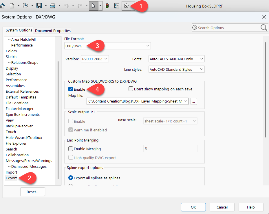
Firstly, we need to enable the option to create DXF Mapping files. To turn this on go to Options > System Options > Export – then change the File Format drop down to ‘DXF/DWG’ and check the box to enable Map File.
Saving the DXF
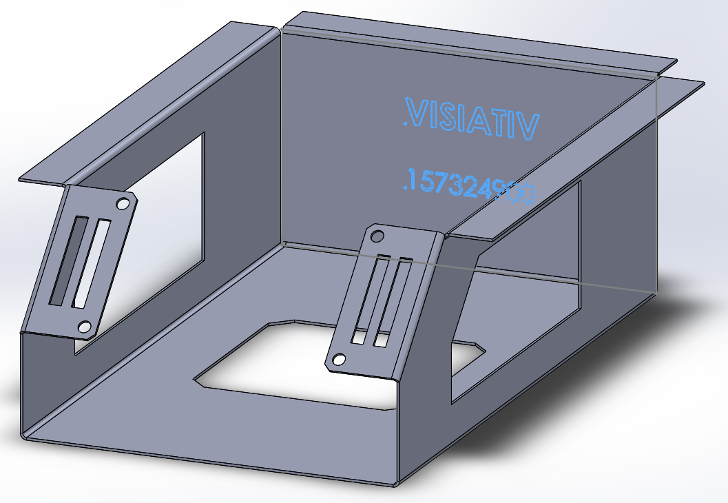
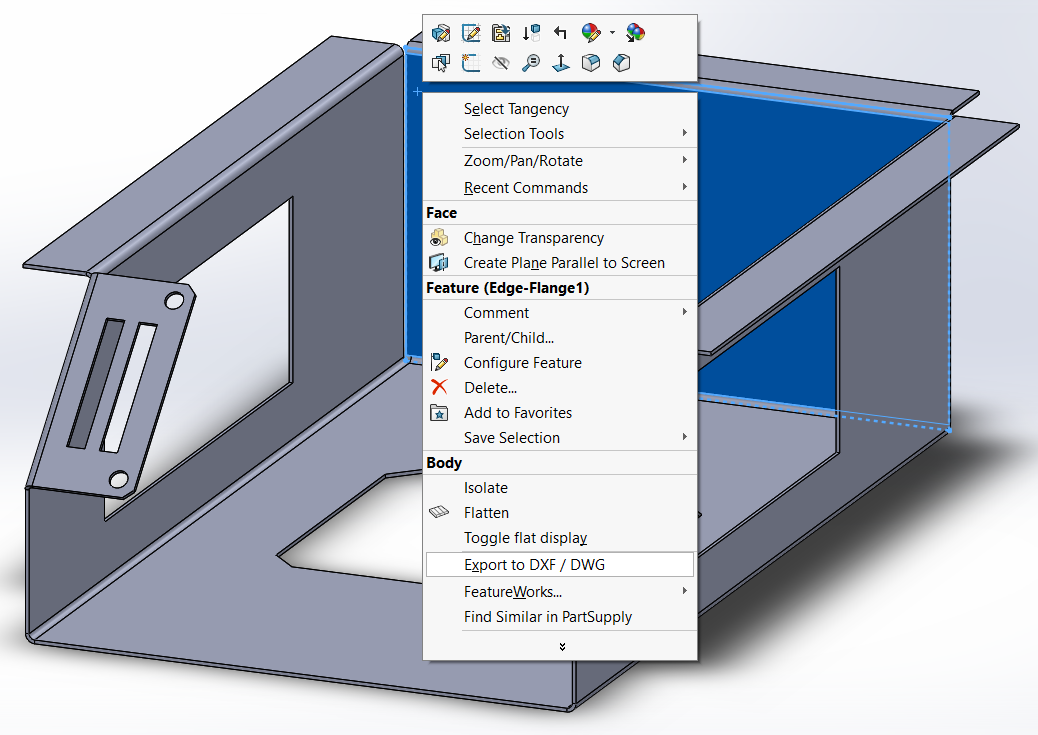
Now that we’ve enabled the mapping file, open your SOLIDWORKS Sheet Metal Part file that you want to convert to a DXF. In this example we have a combination of cuts, etches and bends up and down that we’ll want to capture and easily identify in the DXF file. Right click the geometry and select ‘Export to DXF / DWG’.
 |
 |
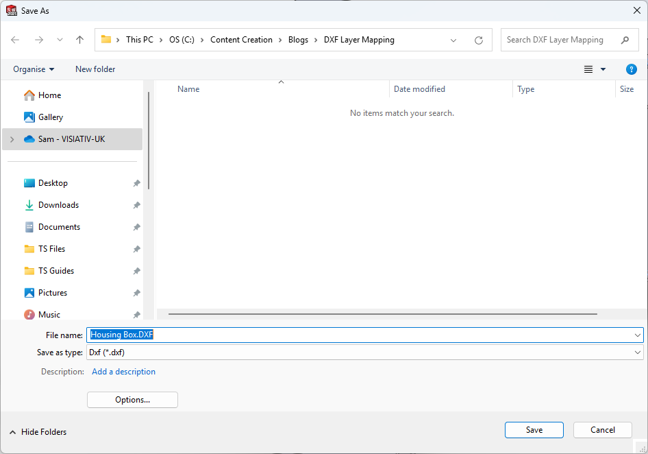
Choose a location for the file, name it and then click ‘Save’.
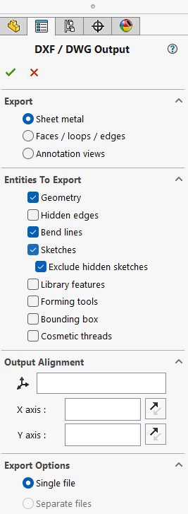
We’ll then choose how we want to translate the file into a DXF. As this is a sheet metal part, we’re mainly concerned with the flat pattern. Therefore, I’ll choose ‘Sheet metal’ and include entities for Geometry, Bend lines and Sketches. Including sketches is essential, as they show the area to be etched on the part.
 |
Adjusting the DXF Mapping File
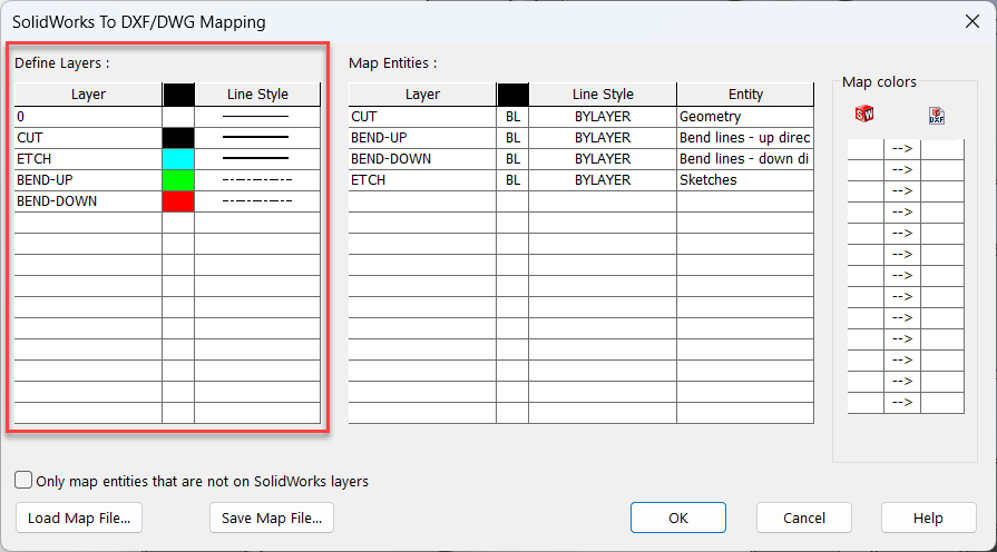
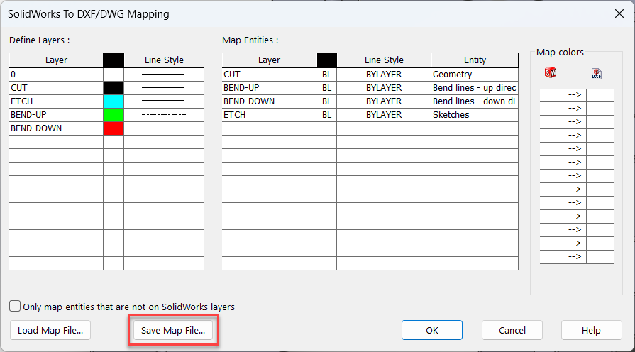
Firstly, we’ll define the layers which will be created in the outputted DXF file. For laser cutting, I’ll create separate layers for cuts, etches, and bends, each with distinct colours and line styles.
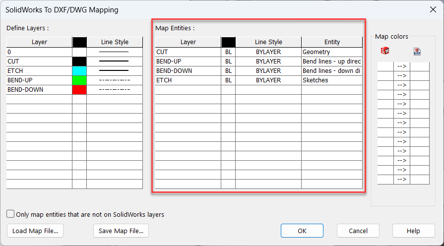
Next, we need to control what model geometry will move to each layer of the DXF. The CUT lines will be all of the edges of the model, therefore we’ll say that the CUT layer will include the Geometry Entities. The BEND-UP and BEND-DOWN layers will have the respective bend line entities. We display the area we want to etch on the model using a sketch. Since we haven’t created a cut or extrusion into the geometry, we’ll say that the ETCH layer contains Sketch entities.
We can also change the line style for each mapped entity individually. However, since we don’t need that level of detail, we’ll choose the ‘BYLAYER’ option, which means the line style will inherit from the layer specified in the previous box
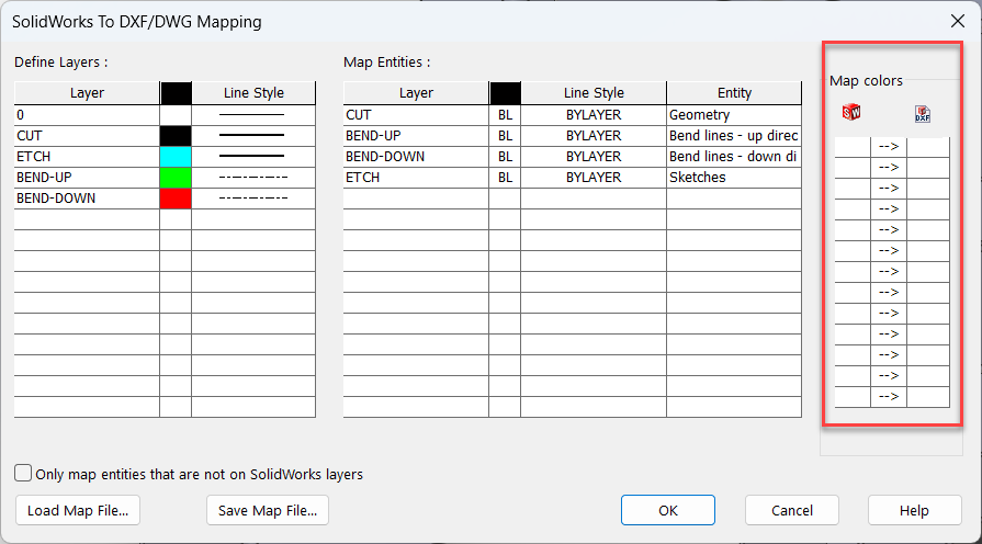
The final section, ‘Map Colors’, is used to control swapping colours of entities between SOLIDWORKS and the exported DXF. This will be Helpful if your company uses specific SOLIDWORKS colours but must adjust them to match a contractor or fabricator. For our purposes we’ll leave this blank.
Before creating the DXF, we can save our mapping settings as a file to avoid repeating these steps next time.
The Result
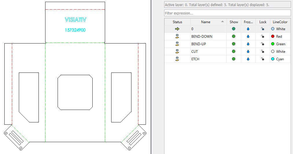
Finally, we can view our exported DXF in a program like DraftSight to see the geometry and the separate layers.
We hope you found this guide useful. You can find more helpful tips and tricks here, or if you’d like to grow your knowledge of SOLIDWORKS, have a look at our official SOLIDWORKS Training Courses.
|
|
About the Author: This tutorial was written by SOLIDWORKS Applications Engineer Sam Barlow. Sam has been with the Visiativ Technical Support Team since 2023 |
|||
|
|
View Sam Barlow’s LinkedIn Profile here.
|
|||