
How to: Create Configured Weldment profiles in SOLIDWORKS
30 January 2026
by Mark Alexander, SOLIDWORKS Applications Engineer.
The SOLIDWORKS Weldment and Structure System functionality allows users to create designs consisting of structural members using 2D and 3D sketches as well as planes and surfaces to define them. You define the members using profiles, much like a sweep feature. While the weldment tools can utilise both configured and non-configured profiles, the structure system can only use configured profiles. It therefore makes sense to configure any custom profiles you create moving forward.
What is a configured profile?
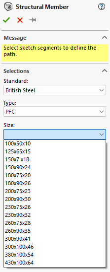
A configured weldment profile is a structural profile (such as a tube, angle, or channel) that includes multiple size variations managed through configurations. Configurations affect physical properties of a model or sketch, in this instance the dimensions of a sketch profile. For example a Parallel Flange Channels (PFC) profile comes in numerous sizes:
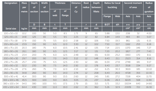
Source: British Steel
Creating the Weldment Profile
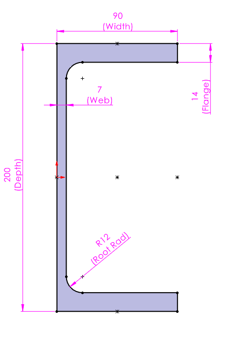
So to use this profile we need to create a sketch containing all the pertinent dimensions:
Creating the Configurations
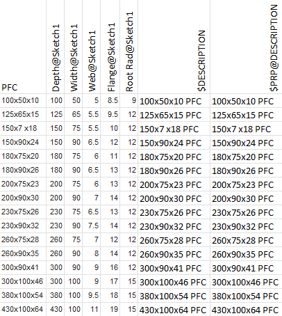
Then we can then create configurations for each of the sizes, with the dimension values relevant to those sizes. Optionally we can include any relevant properties that may be of use – I used an excel design table for this:
Saving the Weldment Profile
The file is then saved as a SOLIDWORKS Library Feature Part (*.SLDLFP) I recommend using the name of the profile in this case I used ‘PFC’ and the sketch must be added to the library. This will be done automatically if the sketch is preselected prior to saving the file as an SLDLFP, however it can be added after be right clicking on the sketch in the feature tree and selecting ‘Add To Library’. The sketch icon will include the letter L to indicate that it’s been flagged:
To use this configured file, save it in a specific folder hierarchy and point SOLIDWORKS to the top-level folder:
Top Level Folder\Standard\Pofile.SLDLFP
Whereas a legacy un-configured file is saved thus:
Top Level Folder\Standard\Profile\Size.SLDLFP
For example, if we decide to put it on the root of the C:\ drive the path for the PFC file would look like this:
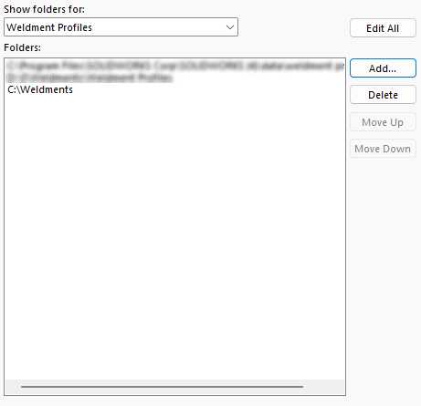
C:\Weldments\British Steel\PFC.SLDLFP
And:
C:\Weldments\ would be added to the file path for Weldment Profiles:
Set up the folders correctly, and the Structural Member Feature properties will look like this:
 |
I hope you found this guide helpful, you can find more tips, tricks and guides here.