

How to: Set up a DriveWorks Xpress Project
30 April 2025
Setting up a DriveWorks Xpress project is an exciting step towards automating your design processes in SOLIDWORKS. DriveWorks Xpress is a powerful tool that allows you to create custom configurations of your models quickly and efficiently. To get started, you’ll need to activate DriveWorks Xpress within SOLIDWORKS, define your project scope, and identify the parameters you want to control.
By using DriveWorks Xpress, we can build intelligence into our model and make changes to it very easily via a form, all from within the SOLIDWORKS UI.
In this blog, we will go through:
- Capturing components and dimensions, ready to apply rules for design changes.
- Building a form, so we can easily change our design.
- Writing rules, so our design changes update the model in a predictable way.
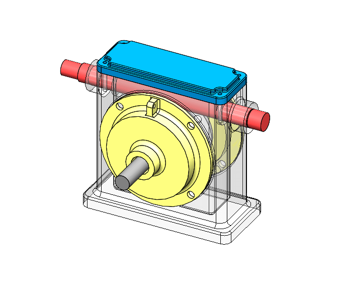
The variations we want for this model are that it may need to be taller, wider, or deeper.
With this in mind, we will need to write rules so the red and grey spindles update in size, while keeping the protrusion constant.
If the Housing size increases, we will also need to change the size of the yellow cover on the front and back, and the hole on the main frame must match to suit as well.
Before starting your project, this is the UI display in the task pane inside SOLIDWORKS
Getting to know the DriveWorks Xpress interface
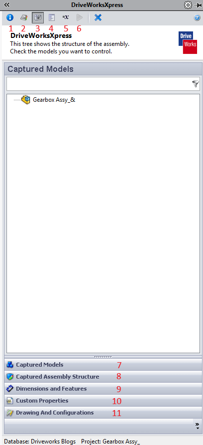 |
1. Welcome: Load different databases and see the location of the database currently in use 2. Projects: Switch between or load different projects 3. Capture: Displays captured models, dimensions, and custom properties 4. Form: Displays properties used in the form and creates forms 5. Rules: Displays rules used to control the model 6. Run: Runs the project 7. Captured Models: Displays models already captured in the project 8. Captured Assembly Structure: Shows the full assembly structure and captures new models in existing projects 9.Dimensions and Features: Displays features and dimensions controlled in the file 10. Custom Properties: Displays the custom properties that will be added to the file when running the projects 11. Drawing and Configurations: Allows switching of configurations and creation of drawings |
Capturing Dimensions
The first thing you need to do after activating DriveWorks Express is to create your project. You can do this by selecting the “Create/Change Database” button and choosing the location where you wish to save your project. Give it a name and select “Open.”
If you have the model open, you can select “Use Open Model.” If not, locate the file after selecting “Browse.”
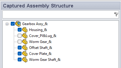
You then need to decide which files will need to be modified by DriveWorks and capture them in the project. You can add these by selecting “Capture” and “Captured Assembly Structure.”
In this example, we will want to capture the housing, both shafts, and the cover plate.
 |
These files should now show on the “Captured Models” tab.
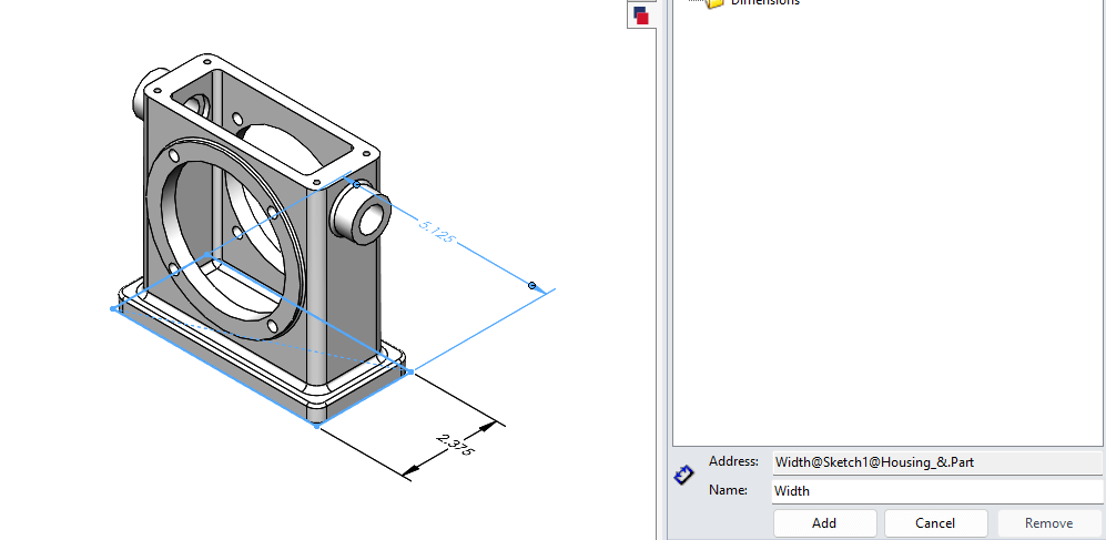
You are now ready to capture dimensions. Open the housing part.
To capture dimensions, switch to the “Dimensions and Features” tab, select a dimension, and select “Add” from the task pane.
Tips
- Using the pin button on the task pane can make adding multiple dimensions quicker.
- Renaming dimensions will make creating rules easier.
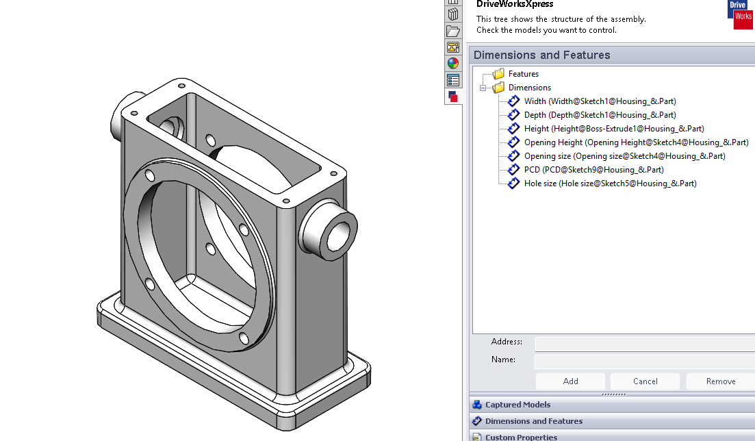
You can see from the list, we plan to control height, width, depth, flange size, and hole size. Remember to capture the respective dimensions from the other parts.
In this example, I have also captured shaft lengths, cover plate sizes, and cover PCD sizes.
Building the Form
Once you have captured all the dimensions and features, you will want to create the form with all the control fields. Although we have captured PCD, shaft lengths, etc., we only want to control height, width, and depth. We will control the other components by applying rules.
To start creating the form, click the “Form” tab and select “Add.”
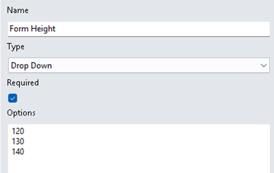 |
From here, we need to give the field a name and choose a type of input field (the options are Text Box, Numeric Text Box, Drop-Down, Spin Button, and Check Box). There is also an option to define this field as required (mandatory) or not.
For this project, we will use a “Drop-Down” so we can predefine the sizes.
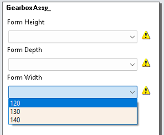
There is also a button to test the form to make sure it has the correct options.
 |
Creating and Applying Rules
Now that the form has been created, we want to start using the values from the form to control our model. We will do this by creating some simple rules.
Go to the “Rules” tab, which will display all the rules and any missing rules. Select the “Edit Rules” button, which displays all the collected dimensions with missing rules.
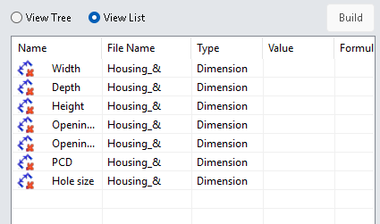 |
You can also select “View Tree” to view every item that is required to have a rule or not; we will look at this at the end.
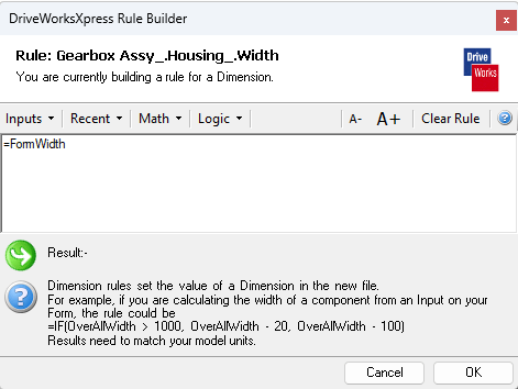
There are a lot of different types of rules we can apply, some very simple like “this dimension equals this form value” (e.g., =FormWidth). More complicated rules can involve IF statements, such as IF (FormWidth<1000, FormWidth, FormWidth-100). If the width is smaller than 1000, the size is will be taken directly from the FormWidth. If it is greater, the size will be FormWidth-100. This can be used to control the width dimension in our model.
 |
Running the DriveWorks Xpress Project
Now that we have collected all the dimensions needed, created the form, and applied rules to control the model, it’s time to run the model.
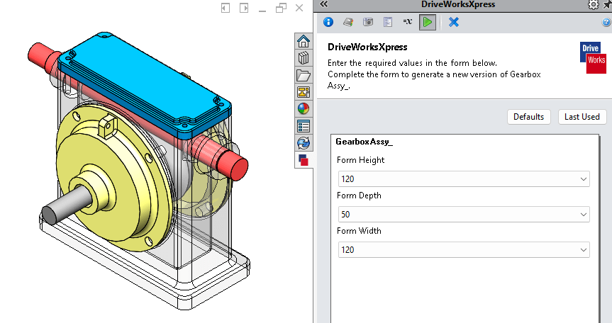
Click the play button and fill in the form.
Finally, select the “Create” tab at the bottom of the task pane.
Although it was not needed for this project, you can also capture drawing files and custom properties to make a full design pack using DriveWorksXpress.
You can also delete files not needed for that variation of the model. However, with DriveWorks Solo, you can suppress features and components and perform model replacements, so you don’t waste time rebuilding features!
If you found this guide useful, and would like to learn more about the other DriveWorks packages please see our DriveWorks product pages
Register for DriveWorks’ Monthly Webinars:
- 2nd Tuesday of the month: Introduction to DriveWorks
- 3rd Tuesday of the month: Using DriveWorks as a 3D Sales Configurator
- 4th Tuesday of the month: Creating a CPQ Solution Using DriveWorks

|
About the author: This tutorial was written by Elite SOLIDWORKS Applications Engineer, James Giddings. James has been with the Visiativ Technical Support Team since 2007. |
|||