
Green Arrows in SOLIDWORKS? A Guide to 3D Interconnect
18 July 2025
If you’ve noticed green arrows appearing on parts or assemblies in your SOLIDWORKS FeatureManager design tree, you’re not alone! These icons represent a feature called 3D Interconnect, which was first introduced in SOLIDWORKS 2017. This functionality is designed to help users work more effectively with files from other CAD systems.
In this article, you’ll find out what those green arrows mean, how 3D Interconnect works, and what steps to take if you need to edit imported files. This is essential reading for anyone working with external suppliers or managing multi-CAD workflows.
 |
What is 3D Interconnect?
Before 3D Interconnect became available, opening third-party CAD files in SOLIDWORKS involved converting them into native SOLIDWORKS documents. This process broke the link to the original file and meant that any updates made in the original CAD software weren’t reflected in your SOLIDWORKS model.
With 3D Interconnect, SOLIDWORKS users can open and use files from other platforms such as Autodesk Inventor, Solid Edge, or PTC Creo without converting them. These files are read-only and maintain a live reference to the original source file on the disk. If changes are made to the file on the disk, those changes will automatically appear in your SOLIDWORKS assembly the next time you open it. 3D interconnect will also maintain the face and edge IDs in SOLIDWORKS to ensure your Assembly Mates stay connected.
Recognising 3D Interconnect Files
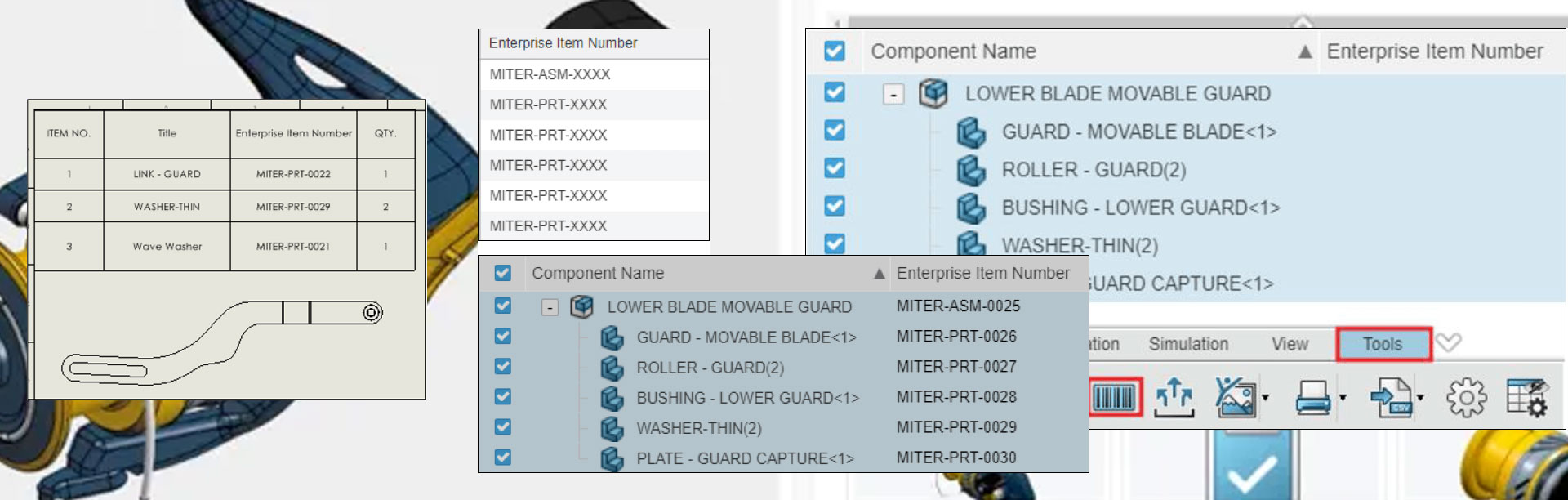
When a file is opened using 3D Interconnect, you’ll see a small green arrows on its icon in the FeatureManager design tree. This indicates that the file has been linked to the original source and hasn’t been converted into a fully editable SOLIDWORKS part or assembly.

3D Interconnect is enabled by default. If you open a STEP or IGES file, for example, it will automatically use this feature unless you change the setting manually.
Editing Files Imported with 3D Interconnect
Since these files are read-only by design, there may be times when you need to make changes. In these cases, you’ve two options:
1. Turn Off 3D Interconnect Before Importing
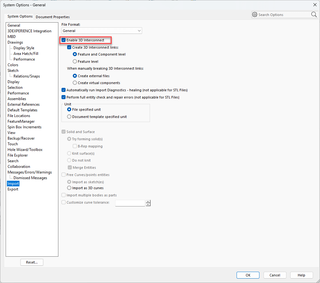
To disable 3D Interconnect and allow SOLIDWORKS to fully convert the file:
- Go to Tools > Options > System Options > Import
- In the General section, uncheck the box labelled ‘Enable 3D Interconnect’
- Re-open the file. It will now be fully editable in SOLIDWORKS, and the green arrows won’t appear
2. Dissolve the Link After Import
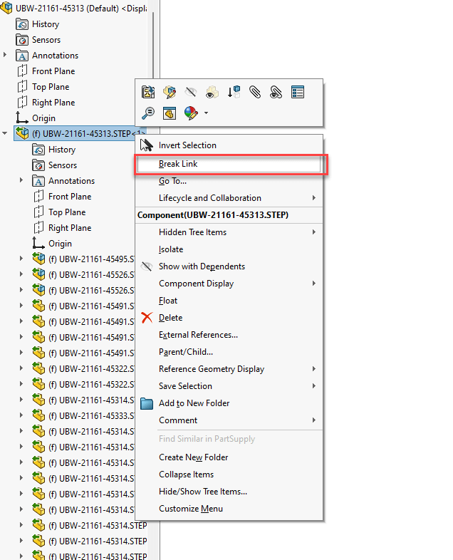
If you’ve already imported a file using 3D Interconnect and want to make changes:
- Right-click the part or assembly in the FeatureManager tree
- Choose ‘Break Link’
- This will break the link to the original source and convert the model into a native SOLIDWORKS file – you’ll also notice the green arrows disappear!
Once dissolved, you can edit the model as you would any standard SOLIDWORKS component.
Latest Versions of SOLIDWORKS: Troubleshooting Import Issues
3D Interconnect uses a different set of file translators from original (pre 2017 legacy translators). If you’re having trouble importing a third-party file or are seeing unexpected results, try importing the file with 3D Interconnect both enabled and disabled. This can help identify the most reliable approach for your specific file format.
With the latest versions of SOLIDWORKS it isn’t possible to change to the legacy translator by disabling 3D Interconnect. However, the old translator can be activated for the time being by adding the following reg keys.
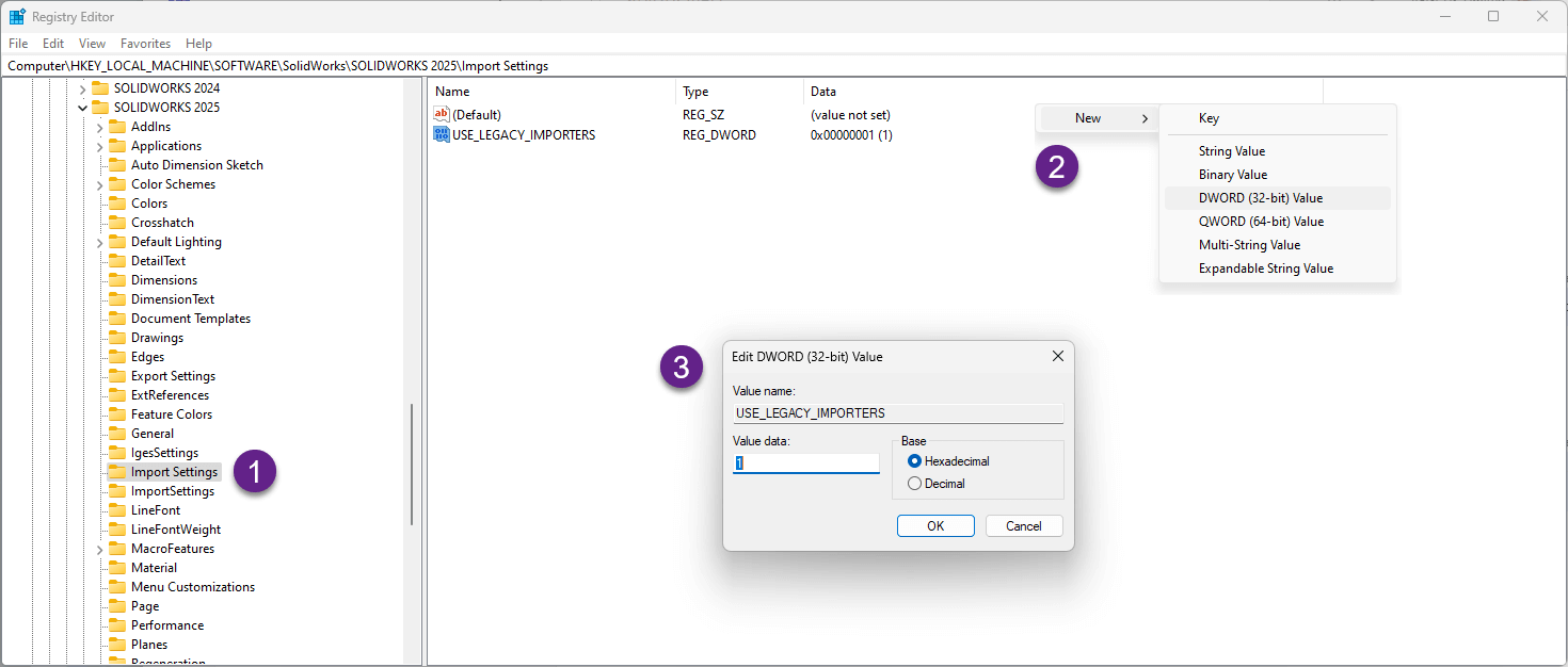
- Browse to HKEY_LOCAL_MACHINE\SOFTWARE\SolidWorks\SOLIDWORKS 2025\(or the same location for your SOLIDWORKS version) and create a new key called ‘Import Settings’
- Right-click and create a new DWORD Value called USE_LEGACY_IMPORTERS
- Right-click on the new value and Modify the value to 1
Note: You’ll need to turn Off 3D Interconnect before importing in order to now use the legacy importer.
Important Notice:
Editing the Windows Registry is intended for advanced users only. Incorrect changes to the registry can cause serious system issues, including software malfunction, data loss or the inability to boot your operating system.
Proceed with Caution:
- Always back up the registry before making any changes
- Only follow instructions from trusted and verified sources
- Double-check all paths and values before applying modifications
Please note: We cannot be held responsible for any damage or data loss resulting from changes made to the Windows Registry. You assume full responsibility for any actions taken based on the information provided. If in doubt please speak to your administrator, or IT professional.
Visiativ UK & Ireland customers requiring assistance or advice can get in touch via. our support page.
Summary
3D Interconnect is a useful feature in SOLIDWORKS that simplifies working with external CAD data. It helps maintain references to original files and avoids unnecessary duplication. However, it also imposes some limitations on file editing. Knowing how and when to disable or dissolve 3D Interconnect gives you greater flexibility in your design workflow.
Visiativ UK & Ireland are here to help you make the most of your SOLIDWORKS software. If you have any questions about 3D Interconnect or any other SOLIDWORKS product, tool or feature, reach out at the link below.
|
|
About the author: This tutorial was written by Elite SOLIDWORKS Applications Engineer and Training Manager, Adam Rose. Adam has been with the Visiativ Technical Support Team since 2010. |
|||
|
|
View Adam Rose’s LinkedIn Profile here.
|
|||