
How to: Create a Custom Symbol in SOLIDWORKS Electrical
15 December 2025
Sometimes we need to represent a component with a custom symbol to convey the connection information better symbolically. To do this, we must know the component circuit and terminals we wish to use/ show. These will also need to be matched to the manufacturer’s part reference. The following steps detail the process for creating a custom symbol in SOLIDWORKS Electrical.
Step 1: Establish the scope of the symbol
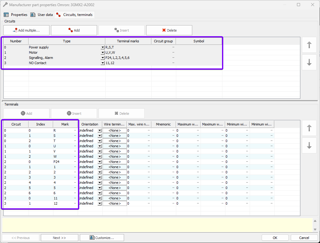
First, define the circuits and terminals you want to include in the symbol. In this example, I’ve already created the manufacturer’s part and selected the circuits and terminals to represent. Circuits group terminals that serve a common function, such as power input or output, while terminals are the individual connection points within each circuit. The image below displays the circuit and terminal details. There are four distinct circuits with a total of 15 terminals.
Step 2: Create a new symbol
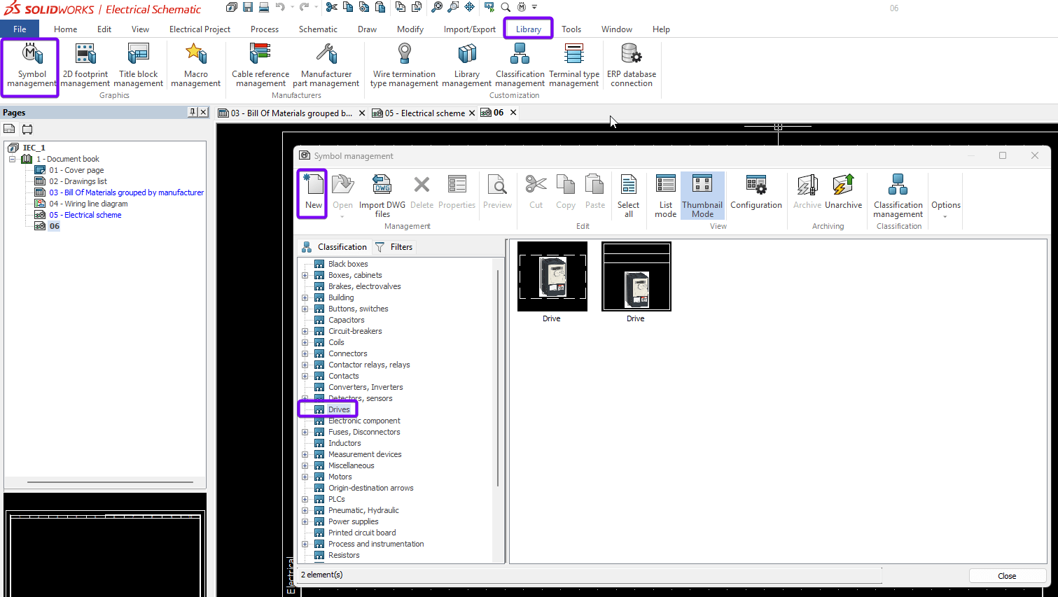
Start by opening the Symbol Management window from the Library tab, as shown below. Select the classification you want to associate with the symbol as this will help us to locate it later. Then, click the “New” button to create a blank symbol. See the image below:
You can now fill in the metadata for the symbol, such as description, manufacturer and mark root.
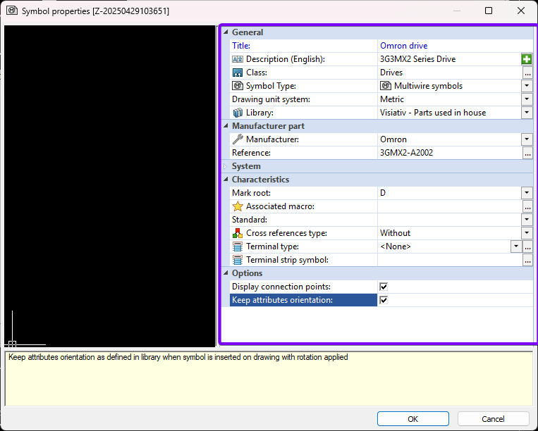
Now, press ok to confirm the data.
Step 3: Drawing the symbol
Open the symbol you created in Step Two to view it in the Symbol Management window. It will appear in a new tab.
You’ll now see the Edit Symbol, Draw and Modify tabs, which you’ll use to create the symbol.
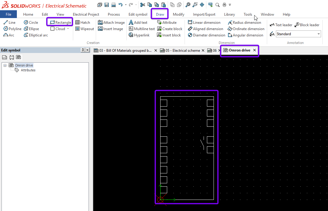
Start by drawing the basic shape for the symbol. In this example, I’ve set the grid spacing to match the project settings, ensuring the symbol’s connection points align with the rest of the schematic. Use the Rectangle tool from the Draw tab to create the outline. Then, add any additional features using the available drawing tools.
You can use lines, arcs, text, images and blocks to build your symbol. Each drawing tool can be used freehand or with precise coordinates entered in the Property Manager while the tool is active.
|
|
Step 4: Adding attributes
Why should we add attributes?
Attributes pull information from the manufacturer’s part data and the symbol properties. This makes the symbol “smarter” and allows it to be reused for similar manufacturer part references.
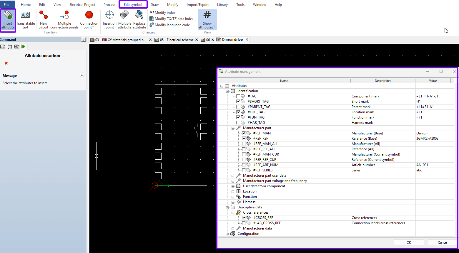
To add attributes, go to the Edit Symbol tab and click the “Insert Attribute” button. This opens a menu where you can choose which information to display as part of the symbol.
In the Attribute Management window, select the attribute you want to include, as shown above, then click OK to confirm. When you hover your cursor over the graphics area, the selected attribute will appear.
|
|
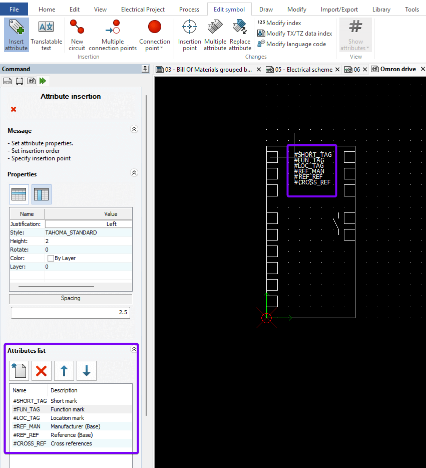
Before placing the attribute, you can adjust its order in the Property Manager using the attribute list and the up/down arrows. Once ready, left-click in the graphics area to place the attribute.
|
|
Step 5: Adding Connection Points
Click the Multiple Connection Point button to efficiently add all required circuit and terminal information at once. Then, click “Add Circuit” to create as many circuits as needed. In the Terminal column, enter the number of terminals for each circuit.
|
|
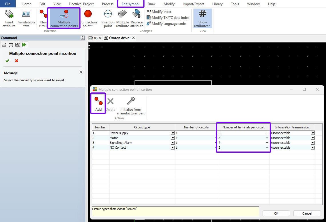
Once all circuits and terminals are added, click OK to begin placing the connection points on the symbol. Keep in mind that terminal IDs are typically specified in the manufacturer’s part.
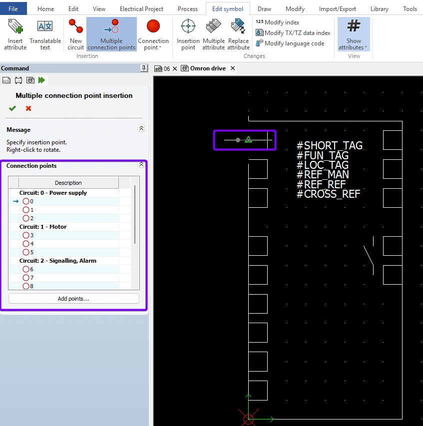
The Property Manager on the left shows which connection point you’re currently placing. While your cursor is in the graphics area, right-click to rotate the connection point. Make sure the grey circle points outward, in the direction of the incoming wire.
Use left-click to place the connection point. For consistency, enable grid snap so all connection points align with the same spacing.
|
|
Step 6: Final Touches
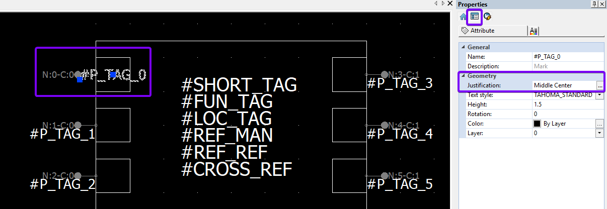
After placing the connection points, it’s time to add the terminal reference attribute inside the symbol. Select the “#P_TAG” attribute, move it into position, then set the text justification to Middle Center. Use the blue handle (visible when the text is selected) to snap the attribute to the grid within the symbol box.
|
|
Once you’re satisfied with the layout, save the symbol to preserve your changes.
Tip: To adjust multiple attributes at once, hold Ctrl while selecting them. You can then change justification or other text properties for all selected items simultaneously.
Step 7: Testing the Symbol
It’s good practice to test your symbol right away by placing it into a live project or a test project. Insert the symbol and assign an appropriate manufacturer’s part to verify it functions correctly.
|
|
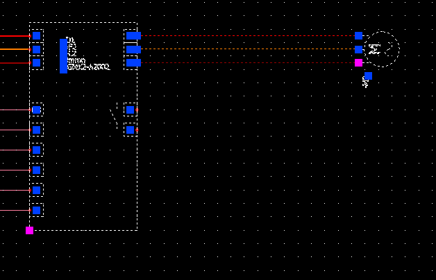
In the example above, the spacing isn’t quite right as my connection points are too far apart compared to other symbols in the project. If your test doesn’t produce the expected result, continue to Step 8.
Step 8: Making Changes
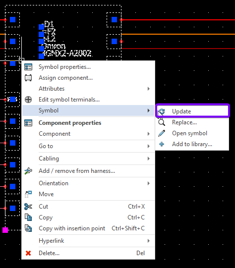
Only complete this step if the symbol requires modification. If the symbol is already closed, right-click the symbol in your test project, scroll to “Symbol” in the contextual menu, and select “Open Symbol.”
Make the necessary changes – for example, adjust the spacing of the incoming and outgoing power connections by either dragging or redrawing the elements. To test your changes, return to the schematic, right-click the old symbol and select “Update.”
Repeat this process until you’re satisfied with the result.
|
|
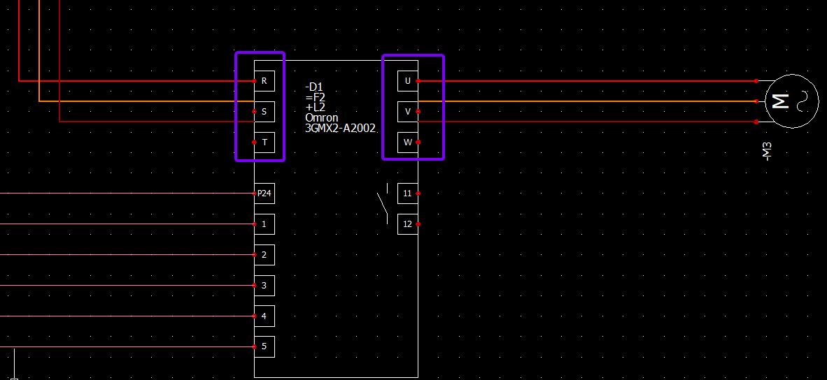
The final symbol should now look much better, with properly aligned connection points and terminal information correctly populated from the manufacturer’s part.
|
|
We hope you’ve found this guide on creating a custom symbol in SOLIDWORKS Electrical useful. For more SOLIDWORKS tutorials, head over to our news and resources pages.
 |
About the author: This guide was written by SOLIDWORKS Applications Engineer, James Kingman. James has been with the Visiativ Technical Support Team since 2024. |
|||
|
|
||||