
How to: Use Automatic Contact Sets in SOLIDWORKS Simulation
28 August 2025
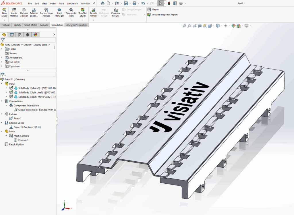
In some cases, SOLIDWORKS Simulation requires contact sets to manage the interactions between bodies. Normally this process happens manually, but Automatic Contact Sets provide an efficient alternative. In this example, two solid body mounts connect through a sheet metal body. These components are not in direct contact, and typically a gasket sits between them. For this study, we exclude the gaskets from the scope. We assume the gasket doesn’t influence the model’s deformation and we apply a bonding link to bridge the gaps.
Why contact sets matter in your simulation
When the study first runs, no faces touch, so the global contact set doesn’t apply to any surfaces. As a result, it’s necessary to build contact sets that connect the sheet metal body to the two mount bodies. Without these contact sets, the sheet metal body remains unconstrained and “flies off” during the simulation.
You must properly define the contact sets to guarantee reliable simulation results. This means identifying the type of contact (e.g., bonded, no penetration) and the faces involved. Doing this creates a realistic interaction between the components and represents how they operate in a real-world context. This step is critical for producing meaningful and trustworthy simulation results.
Save time with automatic contact sets
In this case, 26 gaps need bonded contact sets. Applying these individually takes time, so a more efficient approach is to use the automatic settings within the contact set command to find and add all 26 at once.
To do this, start a new contact set and choose the contact type “Automatically find contact sets.” Since the faces don’t touch, select “non-touch faces” under the options. When this option is active, set a minimum and maximum range. Faces within this gap range are included. Under “components,” select the parts that need the contact sets, or choose the entire assembly if required.
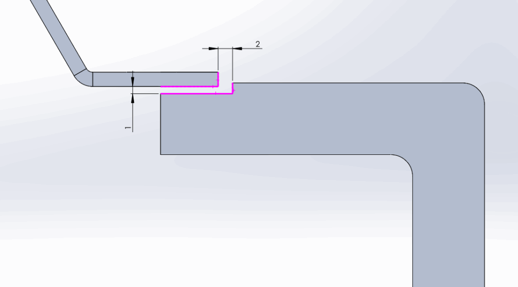
For this study, set the maximum clearance to 1 mm. Some additional gaps in the assembly measure 2 mm, which we don’t want to include, so it’s important to keep the range below this number.
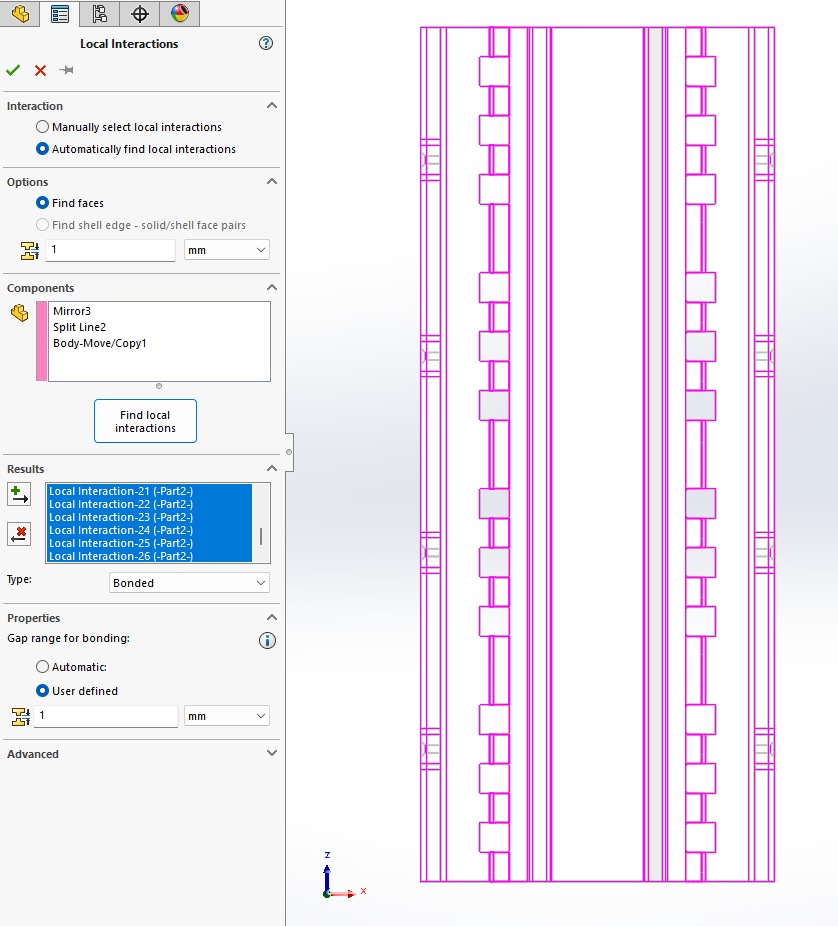
Once all the contact sets are found, select them all using shift select. Ensure they are highlighted, then choose the type of contact. In this case, select “bonded.” The final step is to click the “add” button, which creates the contacts and adds them to the study.
Using Automatic Contact Sets in SOLIDWORKS Simulation saves you time and reduces the chance of missing contacts, it also ensures the model behaves as intended.
If you liked this blog please check out our others here!

|
About the Author: This tutorial was written by SOLIDWORKS Applications Engineer, Cameron Piper. Cameron has been with the Visiativ Technical Support Team since 2021. |
|||
|
|
View Cameron Piper’s LinkedIn Profile here.
|
|||