

How to: Create a SOLIDWORKS Drawing View from a Single Body
13 November 2025
Have you ever been creating a SOLIDWORKS Technical Drawing of a Multibody Part but just wanted to create a view of a single body within the part for detailing?
In this guide we will look at how to quickly import these single bodies into your drawing.
What are Multibodies?
Multibody parts are created within SOLIDWORKS when a single solid part is divided into multiple bodies.
For more information on Multibody Parts, the SOLIDWORKS help files are a good resource.
This can be observed when using certain functions such as the Split tool to divide an existing body. This can also be seen when multiple sketches are used to form separate solids or when leaving the “Merge Result” box is unchecked.
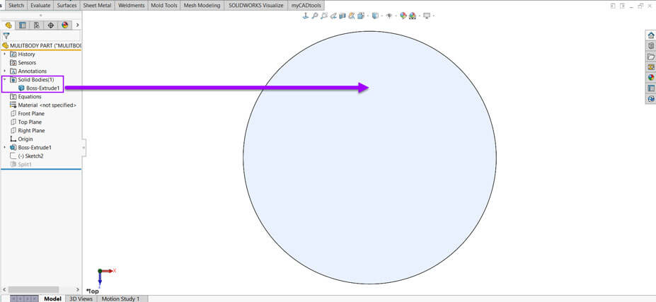
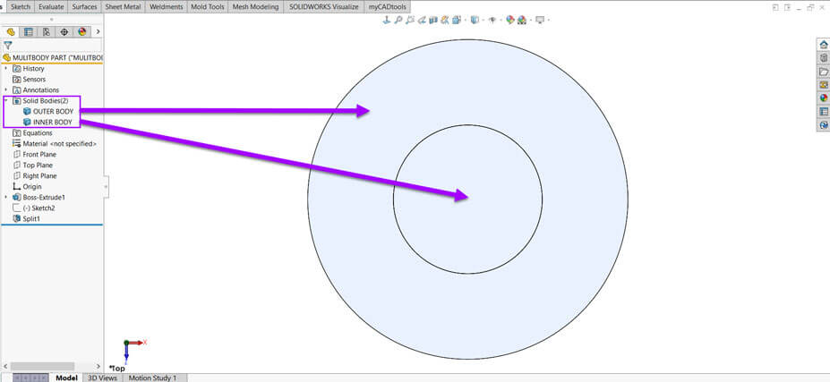
You can quickly check in the feature tree to see if your part has Multibodies.
Within the Solid bodies folder you’ll see all of the individual bodies: Feature Tree > Solid Bodies Folder > Individual bodies listed.
Single Body Part
Multi Body Part
This type of modelling can be very useful as an intermediate step before creating a single body part. This can also be used as an alternative method to creating a simplistic assembly.
Although you should not use this as a direct replacement for assemblies, the process is very useful for certain modelling situations.
Automatically generated Multibodies
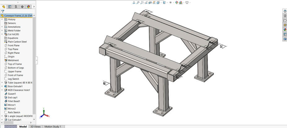
Multibodies are usually implemented as standard when working with certain functions. Common features such as Weldment and Sheet Metal parts can automatically change to working with Multibodies. With these type of features, notice the SolidBodies folder has changed to a folder named Cut List. This allows SOLIDWORKS to manage the cut list body items as a Bill of Materials.
Creating Drawing views of individual bodies
When it comes to detailing a multibody part, SOLIDWORKS Drawings makes it easy to specify the individual body within specific drawing views.
There are three quick ways to work with drawing view Multibodies.
1. Use “Select bodies” within existing Drawing Views
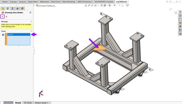
The Select Bodies feature in SOLIDWORKS Drawings allows users to selectively display specific bodies from a multi-body part or assembly within a drawing view. This is useful for focusing on certain components, enhancing clarity and detailing specific parts without showing the entire model.
Place your drawing view on the sheet.
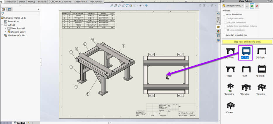
Choose the “Select Bodies” option the to properties Tab.
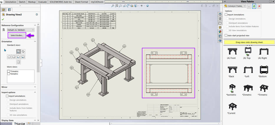
The part will open to choose the body(s) to import. Select green tick to accept the changes and return to the drawing.
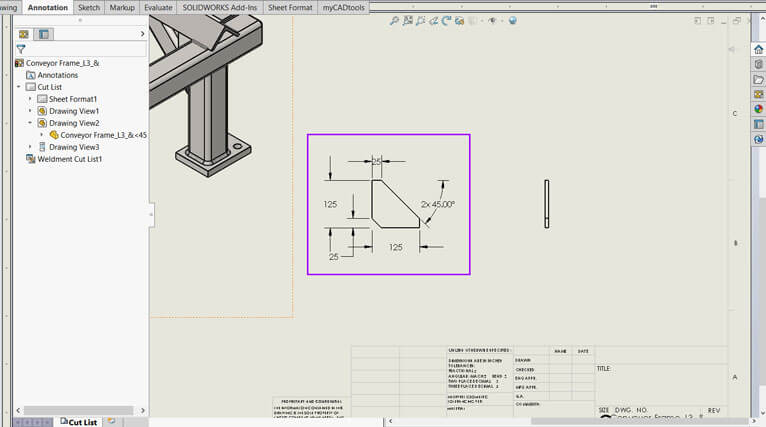
The drawing view now only shows the Body chosen. Now you’re able to add Dimensions in the usual way.
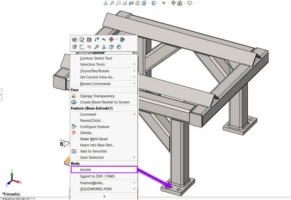
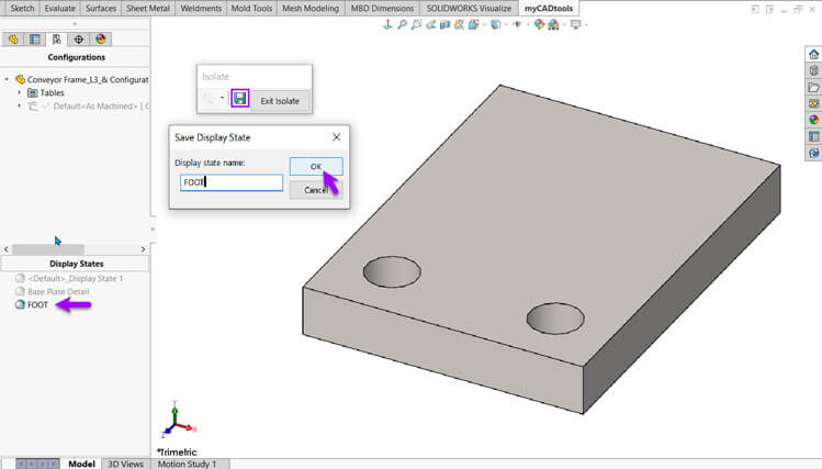
2. Create a display state to use in drawing views
Display States are used to control the visibility and appearance of components but without changing the model’s geometry. They help simplify views, highlight details, manage complex assemblies and streamline documentation, making drawings clearer and more focused.
At the part level right click the body and choose “Isolate”.
In the pop up box choose save to add the new display state.
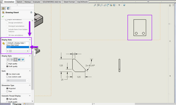
Swap back over to the drawing and add your model view.
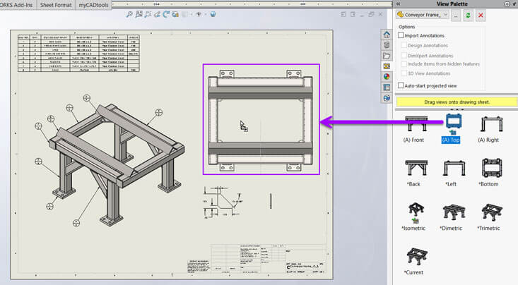
Scroll down in the properties menu and choose your new display state.
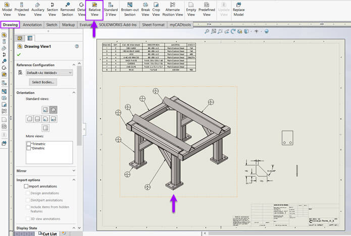
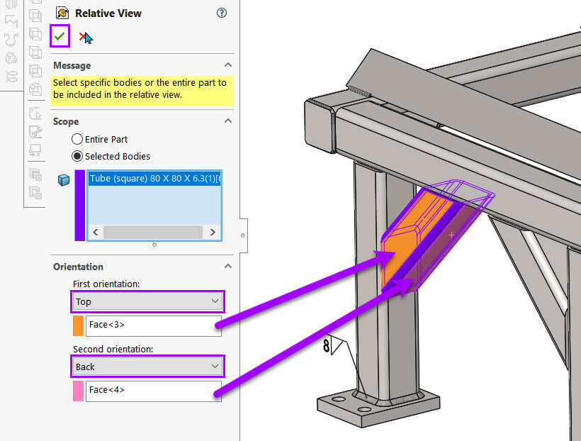
3. Create a relative drawing view
The Relative View command allows you to select bodies to create custom drawing views of; with the orientation based on specific faces or planes of a part or assembly.
In the drawing, preselect the model view to base the new view upon then choose “Relative View” from the “Drawing” tab.
Head back in the part model and hit the “Selected Bodies” option from the menu and click the part you’re interested in.
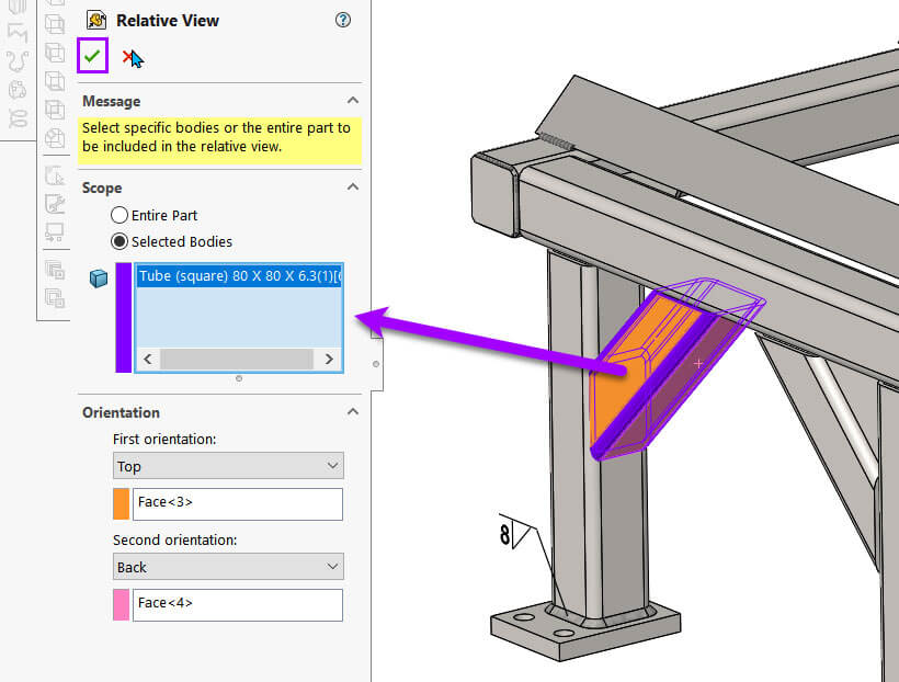
The four selection boxes below allow you to specify two faces that set the orientation of the model view.
Press the green tick to accept the changes.
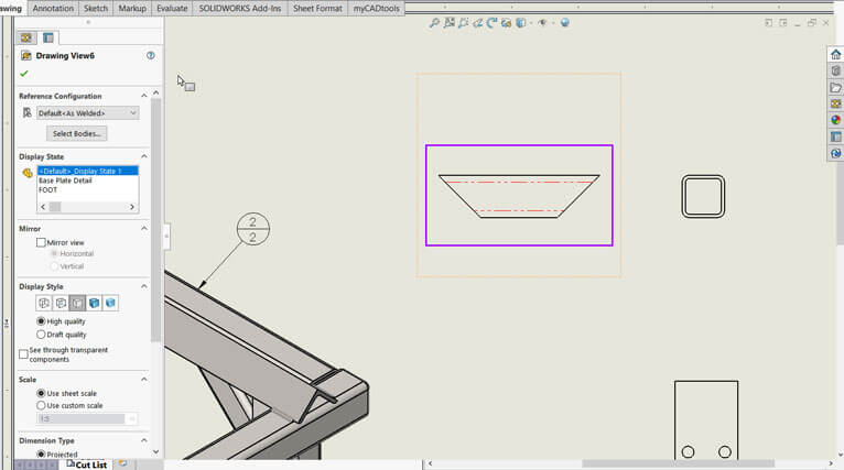
You can then return to the drawing and place your new model view.
Hopefully we have given you a few tips on how to work with Multibodies within a drawing and importing a view of a single body.
For more helpful tips why not check out our other how to articles.
 |
About the author: This guide was written by SOLIDWORKS Applications Engineer, Graeme Billingsley. Graeme has been with the Visiativ Technical Support Team since 2022. |
|||
|
|
||||